


-20-
Model G0580 (Mfd. Since 11/06)
Components and Hardware Needed:
Qty
Trunnion Support Bracket .................................. 1
Table with Trunnions .......................................... 1
Hex Bolts M8-1.25 x 30 ..................................... 2
Hex Bolt M18-1.25 x 80 ..................................... 1
Hex Nut M8-1.25 ................................................ 1
Lock Washers 8mm ........................................... 2
Knobs M10-1.5 ................................................... 2
Tools Needed:
Qty
Wrench 13mm ....................................................1
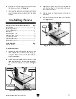
To install the table:
1. Align the trunnion support bracket with the
pins and bolt holes in the body, as shown in
Figure 18.
Table
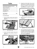
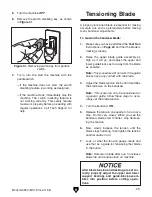
5. Line up the blade with the table slot and posi-
tion the table until the blade is in the center
of the table, then turn the table 90˚ clockwise
and rest it on the trunnion support bracket so
that the hex bolts protrude from the bottom of
each trunnion (see
Figure 22).
Figure 22. Securing trunnion to support bracket.
Trunnions
Knob
Hex Bolt
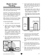
Figure 21. Table insert and pin.
Insert
Pin
4. Remove the table pin and table insert shown
in
Figure 21.
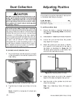
3. Thread the remaining M8-1.25 hex nut onto
the M8-1.25 x 80 positive stop hex bolt,
then thread the bolt into the trunnion support
bracket so it protrudes 2" above the bracket
(see
Figure 20). This will allow the table to
rest approximately level when it is installed.
2. Secure the trunnion support bracket with
the hex bolts and lock washers, as shown in
Figure 19.
Figure 18. Aligning trunnion support bracket with
pins and bolt holes.
Trunnion Support Bracket
Pin
Hole
Figure 19. Trunnion support bracket installed.
Figure 20. Positive stop installed.
2"
Positive Stop
Hex Bolts and
Lock Washers
Summary of Contents for G0580
Page 15: ...Model G0580 Mfd Since 11 06 13 Hardware Recognition Chart...
Page 64: ......