


Model G0524 (Mfd. Since 7/16)
-11-
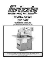
6. Wire main motor as shown in Figure 5.
Figure 5. Main motor wired for 440V.
V6
U1
V1
W1
W6
U6
V5
V2
W5
W2
U2 U5
X
Y
Z
U
V
W
Main Motor
440V
Figure 6. Feed motor wired for 440V.
Feed Motor
440V
U1
V1
W1
W5
W2
V2
V5
U2
U5
Y2
Y2
X2
X2
Z2
Z2
7. Wire feed motor as shown in Figure 6.
Feed motor rotation must be
counterclockwise to prevent perma-
nent damage to caterpiller block. Before
operating, remove belt from feed motor and
test motor rotation.
8. Remove motor cover, then remove cog tooth
belt from feed motor pulley (see
Figure 7).
9. Connect machine to power. Press the Feed
Motor Start Button to check counterclockwise
rotation of feed motor pulley.
—If motor rotation is correct, proceed to
Step 10.
—If motor rotation is incorrect, disconnect
machine from power and swap wire con-
nections X2 and Y2 (see
Figure 6), then
repeat
Step 9.
10. Re-install cog tooth belt and motor cover.
Figure 7. Feed motor components.
Belt
Motor
Pulley
Summary of Contents for G0524
Page 60: ......