Page 2
Drill or punch a 7/8” or 1” hole in the duct at the preferred location and
insert the probe into the hole to mark the enclosure mounting holes.
Remove the unit and drill the two mounting holes.
Clean all drilled holes of debris before mounting the device. Mount
the enclosure to the duct with two sheet metal screws such that the
duct air flow is parallel with the vent holes in the probe (i.e.: air flows
directly into the probe holes). To prevent air leaks, ensure the gasket is
compressed around the probe between the device enclosure and the
air duct. See Figure 1.
The enclosure has a hinged cover with a latch. Open the cover by pulling slightly on the latch on the
bottom of the enclosure, at the same time pulling on the cover. See Figure 2. A 1/2" NPT threaded
connection hole is provided in the side of the enclosure. Screw an EMT connector or cable gland
connector in until tight. A weatherproof conduit or cable gland fitting is recommended. There is an
optional 1/2" NPT to M16 thread adapter and cable gland fitting. See Figure 3.
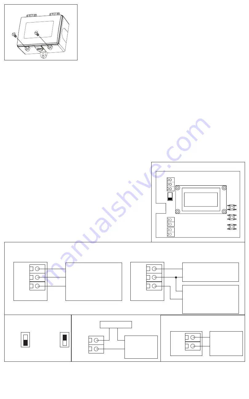
Two security screws are provided which can be installed to help secure the cover once settings and wiring
connections are complete. See Figure 4.
WIRING
Deactivate the power supply until all connections are made to the device to prevent electrical shock
or equipment damage. Use 16-22 AWG shielded wire for all connections (only ground the shield at the
controller end) and do not locate the device wires in the same conduit with wiring used to supply inductive
loads such as motors. Pull at least six inches of wire into the enclosure and complete the wiring connection
according to the wiring diagram. See Figure 5.
This is a 3-wire sourcing device. Connect the plus DC or the AC voltage hot side to the PWR terminal
and the common is connected to the COM terminal. The device
is reverse voltage protected and will not operate if connected
backwards. It has a half-wave power supply so the supply
common is the same as the signal common. Several devices
may be connected to one power supply and the output signals
all share the same common. Use caution when grounding the
secondary of a transformer or when wiring multiple devices
to ensure the ground point is the same on all devices and the
controller. See Figure 6.
The CO
2
analog output is available on the CO
2
terminal. This
signal is switch selectable for either 4-20 mA or voltage output
(0-5 / 0-10 Vdc) and connects to the controller analog input. See
Figure 7.
Check the controller Analog Input to determine the proper connection before applying power. Both
current and voltage signals are referenced to the COM terminal. The current output operates in the active
mode and does not require a loop power supply (the signal current is generated by the transmitter and
must not be connected to a powered input or device damage will result).
Figure 5
Figure 7
Figure 8
Figure 9
Figure 6
Power Supply
Wiring for CO
2
output signal and
24 Vdc power from controller
Wiring for all output and external 24 Vac power
transformer or external 24 Vac power supply
CO
2
COM
PWR
RELAY
TEMP
CO
2
COM
PWR
Analog Input
COMMON
+24 Vdc
COMMON
Digital Input
Analog Input
COMMON
Analog Input
COMMON
COMMON
24 Vac
Controller
Alarm
Controller
24 Vac Transformer /
Power Supply
mA
VOLT
Current
4-20 mA
Voltage
0-5 or 0-10 Vdc
VOLT
mA
Figure 4
PWR
COM
CO
2
TEMP
UP
DOWN
MENU
RELAY
VOLT
mA
Copyright © Greystone Energy Systems, Inc. All Rights Reserved Phone: +1 506 853 3057 Web: www.greystoneenergy.com
IN-GE-CD2DTXXX-03


