background image

Gremo 1250F/1450F Workshop manual

11 Hydraulic diagram

11.1 Hydraulic diagram list

D

e

n

n

a

 h

a

n

d

lin

g

 f

å

in

te

 k

o

p

ie

ra

s

 u

ta

n

 v

å

rt

 s

k

ri

ft

lig

a

 m

e

d

g

iv

a

n

d

e

 o

c

h

 d

e

s

s

 i

n

n

e

h

å

ll 

in

te

 y

p

p

a

s

 f

ö

tr

e

d

je

 m

a

n

 o

c

h

 i

n

te

 h

e

lle

a

n

v

ä

n

d

a

s

 f

ö

n

å

g

o

o

b

e

h

ö

ri

g

ä

n

d

a

m

å

l.

120411

GrArtNo

A

Approved

MJn

1450F

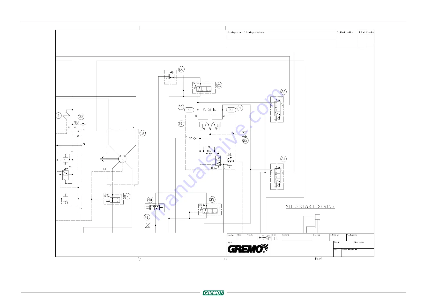
Färdbromsreglering

Fig. 111 Wheel brakes

181

Summary of Contents for 1250F

Page 1: ...Gremo AB 311 51 tran Sweden Tel 46 346 60515 Fax 46 346 60342 www gremo com info gremo se Release Workshop manual in original 1450F 4 1EN Gremo 2019 Gremo 1250F 1450F Workshop manual...

Page 2: ......

Page 3: ...l information 49 3 1 Safety rules during service 49 3 2 Service and maintenance 51 3 3 Volume specifications 52 3 4 Working with oils 52 3 5 Oil requirement specification 54 3 6 Antifreeze requirement...

Page 4: ......

Page 5: ...erator and those who service the machine are familiar with the contents of this Instruction Manual and study it thoroughly before starting and driving or before any preventive maintenance work is done...

Page 6: ...ON Never operate a machine without an instruction manual Refer to your supervisor or the manufacturer if there is anything in the text that you do not understand or if you cannot find what you are loo...

Page 7: ...umentation kit 1 2 5 Ordering documentation Documentation can be ordered from your service dealer or from Gremo AB Always specify the machine number and publication number when ordering The publicatio...

Page 8: ...and common rail fuel system that complies with stage 3B environmental requirements and is approved for running on environmentally friendly fossil free diesel that complies with the requirements in EN...

Page 9: ...thing it is not designed for e g The crane should never be used to lift loads greater than it was designed to lift should never be used to tow or push objects should never be used to lift people The m...

Page 10: ...y regulations Each country has its own national and local safety regulations and it is the responsibility of both the owner and the operator to know and follow these regulations If the recommendations...

Page 11: ...of the surroundings or the machine or other important information that may facilitate understanding or performance of a particular task You can prevent accidents by reading these paragraphs with spec...

Page 12: ...finitions In this Instruction Manual the concepts of front rear right and left on the machine are defined according to the principal direction of travel on roads i e the direction the machine travels...

Page 13: ...r the crane 3 Type plate for the cab 4 Type plate for the machine 5 Type plate for the diesel engine on the rocker cover 6 Type plate for the climate system on the right hand side of the radiator 7 Th...

Page 14: ...or the machine 1 Diesel engine s serial number 2 Machine no XX of XX 3 Machine s total weight 4 Diesel engine s power in KW 5 Machine model 6 Machine s serial number 7 Place of manufacture 8 Country o...

Page 15: ...ing details are shown on the cab s type plate Fig 5 Type plate for the cab 1 Approved according to 2 Model Type 3 Serial no 4 Year of manufacture 5 Weight 1 11 4 Example of crane type plate The follow...

Page 16: ...gine type and number are normally connected to the chassis number must be stated when ordering spare parts If the engine s type plate is not legible the engine s serial number can also be read from th...

Page 17: ...and local workplace regulations must always be followed WARNING The cab is not intended for passenger transport which is why it lacks a seat and seat belt for passengers There is a risk of fatal accid...

Page 18: ...nded with the ignition key in the ignition lock CAUTION Never operate the machine with loose tools binders etc in the cab as these items may injure you if the machine tips over or brakes suddenly Secu...

Page 19: ...of the machine NOTICE Never use the main power switch to turn off the machine as this can cause damage to the machine NOTICE Off road driving requires a lot of experience before you master the machin...

Page 20: ...get caught in moving parts Be careful when working with welders or open flames as hair is flammable Always wear gloves safety footwear safety goggles a safety helmet ear defenders and other necessary...

Page 21: ...mergency stop Check the emergency stop function daily The emergency stop is the red switch with the yellow plate The external emergency stop is located on the right hand ascent into the machine and th...

Page 22: ...machine tips over Fig 13 Opened side window 2 6 Emergency alarm Emergency alarm equipment e g mobile phone or other portable communication equipment must be available When you work outside the machin...

Page 23: ...ser Manual 2 8 Boarding the machine Fig 14 Ascent Use the ladder and hold on to the handle on the bonnet the handle on the cab column and the door handle CAUTION Risk of slipping steps platforms and c...

Page 24: ...checked Place the fully loaded machine on a slight slope 10 12 degrees or a climb of 2 m per 10 m with free rolling movement with no obstacles Stop the machine Engage parking brake Switch off the eng...

Page 25: ...to prevent it from rolling NOTICE If the parking brake does not release it may be necessary to manually release it to move the machine 1 Parking brake cylinder Fig 15 The machine s parking brake can b...

Page 26: ...and tighten until it stops Fig 17 4 Fit the washer and counter locking nut 4 and tighten the nut to release the spring force in the brake cylinder Fig 18 5 Repeat for all four brake cylinders to relea...

Page 27: ...kg even on difficult terrain Off road driving causes large dynamic forces on the machine The machine s own weight plus the load increases the stress in its construction if driven carelessly over diffi...

Page 28: ...cause danger to life Ensure that there are no unauthorised persons within the working area of the crane A risk distance of at least 20 m must be observed DANGER Never work underneath electric power li...

Page 29: ...e brakes are released when the machine starts pulling at about 1 000 rpm If the crane is slewed at this time the machine may tip unexpectedly NOTICE During transportation the crane should be put on th...

Page 30: ...g mode Stop the engine Turn off the main power supply Lock the machine Before leaving the machine always ensure that The machine is parked on a flat surface and not on a slope The parking brake is eng...

Page 31: ...g points on the transport vehicle and machine DANGER Overloading of lifting equipment Danger Lifting equipment must be dimensioned to handle the load Never walk underneath a suspended load Place the m...

Page 32: ...respect of welding see 2 18 Welding Repairs page 32 Gremo should be contacted if any welding is being considered Welding can considerably worsen the machine s abilities and lifespan At the slightest u...

Page 33: ...ome cases this also applies to fire extinguishing and other electronic equipment CAUTION High oil pressure in the hydraulic system Ensure that the hydraulic system is depressurised for service and rep...

Page 34: ...broken tools or broken equipment NOTICE When draining oil or fuel you must take measures to avoid spillage Oil which is dumped freely will cause damage to the environment and may also cause fire Wast...

Page 35: ...tion on your hands will simplify later cleaning Avoid contact with oil especially hot oil If your skin has been in contact with oil wash immediately with soap and water or with a suitable washing loti...

Page 36: ...sing a battery charger designed for a 24 V system 2 18 Welding Repairs NOTICE Prior to beginning any welding read this chapter carefully Turn off the main power switch Disconnect the earth cable betwe...

Page 37: ...he contents of the fire extinguisher tank In order to ensure that the fire extinguisher tank is not accidentally deployed fit the safety screw See Other equipment and optional equipment Fire extinguis...

Page 38: ...is equipped with wet cell batteries there is a risk of corrosive acid leaking from the battery if the machine tips If the machine has tipped over onto one side you should immediately let a Gremo auth...

Page 39: ...As soon as possible try to wash the machine with the high pressure washer and an alkaline cleaning agent The extinguishing agent contains a salt solution which corrodes the engine parts and the cleani...

Page 40: ...formation signs on the machine and its components are always visible and readable Clean dirty signs and replace signs that are damaged are unclear or painted over New signs can be ordered from your se...

Page 41: ...0F 1450F Workshop manual 2 Safety regulations 2 21 Warning signs Fig 25 Warning sign in the event of fire Fig 26 Warning sign for high pressure Fig 27 Operator information for Fogmaker extinguishing s...

Page 42: ...signs Gremo 1250F 1450F Workshop manual Fig 28 Operator information hand held fire extinguisher 2 21 2 On the machine Fig 29 The following warning signs for crushing injuries can be found on the right...

Page 43: ...Gremo 1250F 1450F Workshop manual 2 Safety regulations 2 21 Warning signs Fig 30 Warning sign for crushing injuries moving gate Fig 31 Warning sign for crushing injuries moving mid section 39...

Page 44: ...F 1450F Workshop manual Fig 32 Protective cover for controlling cab tilt The following warning signs can be found on the protective cover for controlling cab tilt on the left side of the machine Fig 3...

Page 45: ...partment The following warning signs can be found in the engine compartment Fig 34 Engine compartment left side 1 Warning for rotating objects 2 Warning sign for crushing injuries under cab Fig 35 Eng...

Page 46: ...l Fig 36 Warning for rotating objects Fig 37 Warning for air conditioning system 1 Type of refrigerant 2 Max pressure NOTICE Special authorisation is required by the person refilling the refrigerant i...

Page 47: ...8 Information sign for air conditioning system 1 Year of manufacture 2 Type of refrigerant 3 Amount of refrigerant 4 Type of oil 5 Pressure in bar 2 21 4 On the crane The following warning signs can b...

Page 48: ...m WARNING There is a large risk of personal injury if substandard towing equipment or incorrect methods are used during recovery towing Therefore always ensure you use towing equipment that can cope w...

Page 49: ...ase of parking brake page 21 and the hydrostatic motor disassembled see 2 22 1 Disassembling the hydrostatic motor page 46 NOTICE You should use the remaining traction of the machine by carefully lett...

Page 50: ...els are locked to prevent it from rolling Fig 42 Hydrostatic motor 1 Remove the screws holding the hydrostatic motor in place on the gearbox 2 Pull the hydrostatic motor out of the gearbox so that the...

Page 51: ...tance 100 m 2 24 Engine and cab heater WARNING The heater must not be used in enclosed spaces such as garages workshops etc unless the exhaust manifold of the heater is connected to an exhaust removal...

Page 52: ...strain related injury In order to avoid that shoulders and neck are exposed to strain during long working periods you should regularly take micro breaks a few seconds and normal breaks a few minutes...

Page 53: ...or broken equipment You are not allowed to service the machine unless you have the correct knowledge to do the work When you handle oil or fuel you should take measures to avoid waste Oil which is dum...

Page 54: ...prop up the machine WARNING When you lift or prop up the machine or parts of the machine make sure that the equipment you use is intended for this purpose is appropriately dimensioned and cannot slip...

Page 55: ...i e the first 2 000 operating hours are described in the Service and Maintenance Manual The daily maintenance includes a systematic inspection of all screw joints This measure is particularly importan...

Page 56: ...Cranab FC12 13 litres 13 litres Crane base crane Loglift Fxx Cab tilt pump 0 7 litres 0 7 litres incl the oil in the filter 3 4 Working with oils CAUTION All work where you may get into contact with o...

Page 57: ...s for fresh ones Always keep an extra overall easily available e g in your car or work shed Not in the machine where it easily gets dirty Cuts and small wounds must be treated immediately by cleaning...

Page 58: ...limits cold starting may be affected but the engine will not be damaged In order to keep wear to a minimum do not exceed the operating limits for extended periods of time Oil changes dictated by the...

Page 59: ...information 3 6 Antifreeze requirement specification 3 6 Antifreeze requirement specification Approved antifreeze is propylene glycol NOTICE Do not mix ethylene glycol and propylene glycol If you hav...

Page 60: ...n Engines should be run on commercial diesel fuel which meets the manufacturer s specifications see sub supplier s documentation for diesel engine NOTICE It is important to only use fuel that meets th...

Page 61: ...ving stains Remove stains of resin paint grease etc before the stain dries Use a soft cloth with one of the approved solvents listed below After the stain has been removed clean according to the above...

Page 62: ...he ground terminal of the welding equipment as close as possible to the welding location Disconnect all computer cables when welding is taking place near the cab engine control climate system DASA Gre...

Page 63: ...ty screw See Other equipment and optional equipment Fire extinguishing system in the Instruction Manual 3 9 2 General The machine is fabricated from high tensile steel in the frames and the articulate...

Page 64: ...anger To avoid serious accidents always follow directions for inflating tyres WARNING Before a wheel is replaced the tyre must first be emptied of air Risk of tyre explosion Danger Empty the tyre by r...

Page 65: ...500 kPa 450 kPa 550 kPa 710 45 26 5 20 T428SB 450 kPa 500 kPa 450 kPa 550 kPa Table 3 Tianli Recommended air pressure Front Tractor Front Tractor Rear Carriage Rear Carriage Tianli With or without ant...

Page 66: ...reased stability Requirement for track use High tyre pressure disadvantages Reduced comfort Increased risk of cutting and puncture damage Increased sensitivity to spot loads Increased formation of whe...

Page 67: ...ir smaller air volume and are therefore more vulnerable to spot loads Rolling resistance and the dynamic forces acting on the wheel rims and suspension components are also higher NOTICE When changing...

Page 68: ...64...

Page 69: ...ides electrically controlled diffusers with fuel at a very high pressure The fuel pump also circulates the fuel through a fuel filter and primary filter which is why the tank is fitted with a fuel sup...

Page 70: ...nsor 10 Condense filter CAUTION The high pressure fuel lines from the fuel pump and the fuel distributor on the engine contain fuel at very high pressure Never loosen the pipe couplings or similar in...

Page 71: ...t flow lubricating oil cooler 4 Coolant flow through the cylinders 5 Coolant flow from the cylinders to the top 6 Coolant flow between the cylinders 7 Coolant flow to the thermostat housing 8 Coolant...

Page 72: ...ust system with particulate filter Fig 48 DPF particulate filter 4 4 1 General The engine installed in this machine is a 3B engine that complies with the requirements outlined in the 97 68 EG directiv...

Page 73: ...ut 700 800 C takes place after the soot level is too high 4 Filter cleaning replacement after about 3 500 hours or when the soot level is so high a red engine lamp goes on Fig 49 The regeneration proc...

Page 74: ...ghts up after 3 500 hours or when a red check engine lamp is lit flashes The DPF filter must then be replaced The next time the filter can be cleaned using the correct equipment 4 5 Replacing drive be...

Page 75: ...elt 2 Lift the belt tensioner fit on the drive belt and let the tensioner return to its normal position 3 Check that the belt is centred on all pulleys 4 Adjustment Do not use excessive force in the o...

Page 76: ...72...

Page 77: ...as two gears and develops a variable torque that is easily controlled using the potentiometer in the left panel This section describes how to check and replace the gearbox oil as well as the gearbox s...

Page 78: ...omponent position 2 5 3 1 4 6 Fig 54 Bogie axle component position 1 Differential housing drain 2 Differential housing level plug 3 Differential housing filling 4 Differential housing dipstick 5 Manua...

Page 79: ...ange Switch off the engine and cut the main power supply Place a container under the differential housing s drain plugs position 1 Remove the three drain plugs position 1 at the bottom of the axle and...

Page 80: ...making sure the seal is correctly in place Remove the bogie housing s filling plug position 3 Fill the bogie housing with new oil until the oil level is flush with the level opening position 2 For vo...

Page 81: ...per brake cylinder 151 by loosening the bolts 152 M8 NB do not touch the bolts 170 M6 the adjustment screw is accessed 158 Remove this screw 158 and the counter locking nut 159 completely and clean th...

Page 82: ...78...

Page 83: ...horizontally by numbers In the case where a wire ends on a certain diagram there will be a reference square at the end of the cable giving the coordinates of the diagram and position where the cable...

Page 84: ...Workshop manual 6 2 Component position of fuse groups and relays Fig 59 Position of distribution boxes Pos Location Fuses Relay A Right engine compartment F51 F60 F99 F101 K30 31 K60 at rear B Distri...

Page 85: ...ngine compartment Fuse Nominal current A Function F51 40 Main fuse for fuses F12 F24 F46 F49 F50 F52 20 Diesel heater F53 20 Back up 00 002 F54 30 Cummins engine F55 25 Tank pump for hydraulic oil vac...

Page 86: ...er relay K60 pre heating F101 150 Main fuse for cab card 6 2 2 Fuse and relay list distribution box in cab Fig 61 Distribution box in cab Fuse Nominal current A Function F1 5 Operation of ECU charge i...

Page 87: ...rd warning lights main power cutout F13 10 Operation of starting relay relief relays K1 K3 F14 10 Driving lights F6 F7 F15 7 5 Winch Gate operation operator s seat tilt interior lighting mechanic s la...

Page 88: ...right side F33 15 Working lights low left side F34 15 Working lights low right side F35 10 Working lights roof cab rear left side F36 10 Working lights roof cab rear right side F37 15 Working lights c...

Page 89: ...Overload protection relay for ignition lock K3 Overload protection relay for ignition lock K4 Working lights roof front K5 Working lights roof sides K6 Working lights low sides K7 Working lights roof...

Page 90: ...t mode K25 Float mode K30 Start barrier relay K31 Power relay Start diesel K60 Power relay Pre heating K1 K25 are located in the Distribution box K30 K31 and K60 are located at the main switch Other r...

Page 91: ...12 Distribution box Cab card Roof cable harness JPT 15 pin A13 Distribution box Cab card Roof cable harness JPT 15 pin A14 Distribution box Cab card Extra feeds JPT 21 pin A15 Distribution box Cab car...

Page 92: ...in X3 Distribution box Floor engine cable harness CPC 37 pin X5 Distribution box Floor cab chassis cable harness CPC 24 pin X6 Distribution box Floor gearbox cable harness CPC 24 pin X8 Distribution b...

Page 93: ...rmrest panel Deutsch 6 pin 40 IQAN XA2 A6 Cab damping MT 42 pin X45 Wipers front FF 4 pin X46 Wipers rear FF 4 pin X47A Driving lights left MNL 9 pin X47A Driving lights right MNL 9 pin X50 Seat frame...

Page 94: ...77 Rotating warning light MNL 2 pin X78 Forward Backward pedal FF 4 pin X79 Diff front rear FF 4 pin X80 X84 Activation of the driver s seat brake 2 pin round X85 Crane light FF 4 pin X86 Right Left W...

Page 95: ...5 Hydraulic oil cooler 6 Hydraulic tank 7 Return filter 7 2 Hydraulic oil return filters 7 2 1 Return oil filter Fig 63 Replacing hydraulic oil return filter The oil in the hydraulic system is cleane...

Page 96: ...rt 7 4 Off line filter hydraulic oil 7 4 1 Off line filter general The Off line filter which is a Kleenoil By Pass Filter model is mounted on the right hand side of the hydraulic oil tank The filter i...

Page 97: ...e 2 PL Signal pressure 7 5 1 General The working hydraulics pressure can be checked in the Hydraulics window in GreControl which is accessed by pressing in the main window The pressure for the working...

Page 98: ...ured does not correspond to the specified standard pressure contact your service provider 7 5 2 Checking Max Pressure Fig 65 Checking Max Pressure Checking Max Pressure hydraulics 1 Go to the Hydrauli...

Page 99: ...is adjusted in accordance with the description below B A Fig 66 Adjustment of Max Pressure 1 Adjust using the adjustment screw position A on the valve block located on the inside of the frame to the...

Page 100: ...ometer 2 5 The pressure difference between manometer 1 and manometer 2 should match the normal pressure for the Pressure Difference PX PL for the crane in question as per table Table 4 Hydraulic press...

Page 101: ...lock nut and reset the Max power on the rotator in GreControl to the previously noted value 5 Switch off the machine remove the manometers and refit the protective caps on the measurement outlets NOT...

Page 102: ...98...

Page 103: ...sed air tank which is equipped with automatic draining is mounted under the diesel tank The pressurised air outlet is mounted in the left hand toolbox branch deflector F RSIKTIGHET Wear protective gog...

Page 104: ...Pressurised air system 8 2 Pressurised air diagram Gremo 1250F 1450F Workshop manual 1 Air filter 4 Pneumatic operator s seat 2 Compressor 5 Quick connection 3 Pressure regulator 6 Accumulator tank 10...

Page 105: ...nd audible alarm signal in the alarm panel 3 Flashing warning lamp in the cab roof 4 The fire extinguisher tank is triggered if the semi automation is disconnected by pressing the emergency stop turni...

Page 106: ...tem activates both a visible and audible alarm signal in the alarm panel but the fire extinguisher tank is not triggered Disabling the alarm fire extinguishing system If you have verified that it is a...

Page 107: ...ire has been established and any faults are rectified You are required to observe and follow the instruction signs on the machine The fire extinguishing system must be inspected once a year by authori...

Page 108: ...104...

Page 109: ...Gremo 1250F 1450F Workshop manual 10 Wiring diagram 10 1 Power supply 10 Wiring diagram 10 1 Power supply 105...

Page 110: ...106...

Page 111: ...Gremo 1250F 1450F Workshop manual 10 Wiring diagram 10 1 Power supply Fig 75 Power supply main feeds 107...

Page 112: ...108...

Page 113: ...Gremo 1250F 1450F Workshop manual 10 Wiring diagram 10 1 Power supply Fig 76 Power supply Cab card 109...

Page 114: ...110...

Page 115: ...E C B A Z B A 1 2 3 4 5 6 7 8 9 10 11 12 13 14 15 16 17 18 19 20 O Z T Y X U V S R Q P J N M L K I H G F D E C Ej skalenlig Anm Skala Ritn nr Ers tter MED PCB KRETSSCHEMA RJN Ritad Konstr Material De...

Page 116: ...112...

Page 117: ...Gremo 1250F 1450F Workshop manual 10 Wiring diagram 10 1 Power supply Fig 78 Driving lights 113...

Page 118: ...114...

Page 119: ...LJUSBL VIT SVART X72 Dx Sx 30 R L 56a 56b 56 L J 53 53b 31b 53c 15 HELLJUS HALVLJUS OPTISKSIGNAL H 15 1 0 2 8 S 533193 6 3 1 10 1 7 5 87A 87 30 85 86 K16 21 205 17 004 17 000 OCH VARNINGSBLINKERS R1A...

Page 120: ...116...

Page 121: ...Gremo 1250F 1450F Workshop manual 10 Wiring diagram 10 1 Power supply Fig 80 Working lights 117...

Page 122: ...118...

Page 123: ...Gremo 1250F 1450F Workshop manual 10 Wiring diagram 10 1 Power supply Fig 81 Windshield wipers 119...

Page 124: ...120...

Page 125: ...Gremo 1250F 1450F Workshop manual 10 Wiring diagram 10 1 Power supply Fig 82 Windshield wipers with side wipers 121...

Page 126: ...122...

Page 127: ...ning Status Dat 120509 Ant Ant Det nr Material Konstr Ritad RJN KRETSSCHEMA MED PCB Ers tter Ritn nr Skala Anm Ej skalenlig C E D F G H I K L M N J P Q R S V U X Y T Z O 20 19 18 17 16 15 14 13 12 11...

Page 128: ...124...

Page 129: ...Gremo 1250F 1450F Workshop manual 10 Wiring diagram 10 1 Power supply Fig 84 Heating ventilation and AC Lokab 125...

Page 130: ...126...

Page 131: ...Gremo 1250F 1450F Workshop manual 10 Wiring diagram 10 1 Power supply Fig 85 Cab and Mech lighting Chair heater tilt and chair brake Rotation light 127...

Page 132: ...128...

Page 133: ...11 12 A7 7 22 000 H H A12 4 A18 17 20 000 A12 8 V F22 BLAD 1 O T Y X U V S R Q P J N M L K I H G F D E C B A Z B A 1 2 3 4 5 6 7 8 9 10 11 12 13 14 15 16 17 18 19 20 O Z T Y X U V S R Q P J N M L K I...

Page 134: ...130...

Page 135: ...7CC HYDRAULMOTORVARV JORD 24 X6 17 2 1 n 3 3 9 10 18 102 18 101 18 000 08 000 08 102 08 306 min E X24 FR MRE HASTIGHETSPEDAL max A B C 10 012 D 10 011 X25 BAKRE HASTIGHETSPEDAL min max 08 103 10 012 0...

Page 136: ...132...

Page 137: ...SPEDAL X105 FR MRE HASTIGHETSPEDAL HYDRAULMOTORVARV A2 9 18 101 A8 6 10 011 A8 9 10 012 IQAN XA2 A0 IQAN XA2 A0 X32 29 X32 42 K19 86 BLAD 23 X33 12 X33 13 IQAN XA2 A1 IQAN XA2 A1 08 331 A9 2 08 330 A9...

Page 138: ...134...

Page 139: ...ning Status Dat 120509 Ant Ant Det nr Material Konstr Ritad RJN KRETSSCHEMA MED PCB Ers tter Ritn nr Skala Anm Ej skalenlig C E D F G H I K L M N J P Q R S V U X Y T Z O 20 19 18 17 16 15 14 13 12 11...

Page 140: ...136...

Page 141: ...2 8 1 7 M PUMP OIL FILLING DIESEL FILLING PUMP M S 533215 9 10 10 9 9 10 TANK BOARD 611163 BLAD 0 F58 P2 7 55 000 P2 8 BLAD 0 F55 POWER BOARD P2 6 56 000 F56 BLAD 0 55 001 13 200 55 000 56 000 AIR VA...

Page 142: ...138...

Page 143: ...Dimension Ben mning Status Dat 120509 Ant Ant Det nr Material Konstr Ritad RJN KRETSSCHEMA MED PCB Ers tter Ritn nr Skala Anm Ej skalenlig C E D F G H I K L M N J P Q R S V U X Y T Z O 20 19 18 17 16...

Page 144: ...140...

Page 145: ...3 JORD 4 SIGNAL 04 000 BLAD 1 F4 CABIN BOARD ALLHJULSDIFT DIFFSP RR OCH GRIND VINSCH R1A Nr RJN 1450F Sign Inf rd Datum 120509 Cummins QSB ndring och eller medd nr Anm Ersatt av BLAD 16 Mod nr mne Dim...

Page 146: ...142...

Page 147: ...rsatt av BLAD 17 Mod nr mne Dimension Dat Godk Stand enl Material Mod nr mne Dimension Ben mning Status Dat 120509 Ant Ant Det nr Material Konstr Ritad RJN KRETSSCHEMA MED PCB Ers tter Ritn nr Skala A...

Page 148: ...144...

Page 149: ...UPP HUVUD BOM V NSTER H GER KRAN SV NG 10 528 4 18 10 529 32 10 530 3 17 31 10 525 10 526 10 527 10 524 10 523 X15 2 16 30 08 603 08 602 08 601 30 16 2 08 601 08 602 08 603 08 601 08 601 3 17 31 08 60...

Page 150: ...146...

Page 151: ...940 09 951 1 2 X36 09 951 09 940 4 3 V NSTER PALETT 7 5 1 X8 A4 7 CABIN BOARD BLAD 2 09 000 24 001 A4 1 10 000 A8 16 A6 12 09 940 09 951 A6 11 A6 1 08 000 2 1 09 931 09 920 CAN H CAN L 09 931 CAN H 0...

Page 152: ...148...

Page 153: ...19 08 144 13 14 12 25 08 011 08 012 08 012 08 011 9 12 8 11 C B A HYDRAULOLJE NIV C B A P I FILTERTRYCK TRANS FILTERTRYCK ARB HYD I P A B C BR NSLENIV A B C X1 C B A I 24 13 11 7 8 11 9 10 08 115 08 1...

Page 154: ...150...

Page 155: ...onstr Ritad RJN KRETSSCHEMA MED PCB Ers tter Ritn nr Skala Anm Ej skalenlig C E D F G H I K L M N J P Q R S V U X Y T Z O 20 19 18 17 16 15 14 13 12 11 10 9 8 7 6 5 4 3 2 1 A B Z A B C E D F G H I K L...

Page 156: ...152...

Page 157: ...ABIN BOARD O T Y X U V S R Q P J N M L K I H G F D E C B A Z B A 1 2 3 4 5 6 7 8 9 10 11 12 13 14 15 16 17 18 19 20 O Z T Y X U V S R Q P J N M L K I H G F D E C Ej skalenlig Anm Skala Ritn nr Ers tte...

Page 158: ...154...

Page 159: ...Status Dat 120509 Ant Ant Det nr Material Konstr Ritad RJN KRETSSCHEMA MED PCB Ers tter Ritn nr Skala Anm Ej skalenlig C E D F G H I K L M N J P Q R S V U X Y T Z O 20 19 18 17 16 15 14 13 12 11 10 9...

Page 160: ...156...

Page 161: ...Temp sensor Mixed air Styrenhet ECC 8002414 Vit J1 5 Gr n 300mA J1 4 Brun 300mA J1 7 Svart r d 300mA J1 17 Bl vit 300mA J1 8 Orange J2 11 Orange J2 4 Gr J2 14 Gr J2 7 Lila J2 12 Lila J2 5 Rosa J2 13 R...

Page 162: ...158...

Page 163: ...PV BROMS BAK 5 PV BROMS FRAM 21 508 4 21 507 21 507 21 508 21 510 1 2 1 2 X17 21 509 21 509 6 19 6 20 21 507 21 508 21 509 21 510 B 21 012 21 011 D 08 334 25 VIT OUTPUTY BRUN 24V BL GND LUTNINGSGIVARE...

Page 164: ...160...

Page 165: ...012 2 1 BROMSPEDAL 3 21 102 21 011 21 101 08 334 A9 8 A10 8 08 334 A10 4 21 012 21 011 A10 10 21 012 BLAD 1 A9 9 A9 15 21 011 A11 10 X34 21 012 29 42 21 011 21 101 10 11 21 102 08 334 25 I P P I Y Y...

Page 166: ...162...

Page 167: ...7 K5 7 R3 R2 R1 TGT 21 Boggie v ner 24V TGT 19 Boggie v upp TGT 20 Boggie v flytl ge R4 1 2 3 8 GND 24V Bakgrundsbelysning 9 10 K6 1 K6 2 K6 3 K6 8 K6 9 K6 10 5 K6 5 LED 20 Boggie v flytl ge 6 K6 6 7...

Page 168: ...164...

Page 169: ...10 Krantilt fram t TGT 11 Krantilt bak t R4 1 2 3 8 GND 24V Bakgrundsbelysning 9 10 K6 1 K6 2 K6 3 K6 8 K6 9 K6 10 LED 12 Terr ngfart 5 K6 5 6 K6 6 7 K6 7 R3 R2 R1 TGT 19 Parkeringsbroms 24V TGT 21 Fa...

Page 170: ...166...

Page 171: ...1 12 13 14 15 16 17 18 19 20 O Z T Y X U V S R Q P J N M L K I H G F D E C Ej skalenlig Anm Skala Ritn nr Ers tter MED PCB KRETSSCHEMA RJN Ritad Konstr Material Det nr Ant Ant 120509 Dat Status Ben mn...

Page 172: ...168...

Page 173: ...Gremo 1250F 1450F Workshop manual 10 Wiring diagram 10 1 Power supply Fig 106 Active bogie 169...

Page 174: ...170...

Page 175: ...Gremo 1250F 1450F Workshop manual 10 Wiring diagram 10 1 Power supply Fig 107 Active bogie 171...

Page 176: ...172...

Page 177: ...ing and Gate 4 Wheel brakes 5 Working pump and LS Activation 6 Bogie lift and mid section stabilisation 6B 7 Active Bogie lift and mid section stabilisation 8 Hydrostatic pump 9 Hydrostatic motors 10...

Page 178: ...174...

Page 179: ...st Denna handling f r inte kopieras utan v rt skriftliga medgivande och dess inneh ll f r inte yppas f r tredje man och inte heller anv ndas f r n got obeh rigt ndam l 120411 GrArtNo A Approved MJn 14...

Page 180: ...176...

Page 181: ...ydraulic diagram list Denna handling f r inte kopieras utan v rt skriftliga medgivande och dess inneh ll f r inte yppas f r tredje man och inte heller anv ndas f r n got obeh rigt ndam l 120411 GrArtN...

Page 182: ...178...

Page 183: ...aulic diagram list Denna handling f r inte kopieras utan v rt skriftliga medgivande och dess inneh ll f r inte yppas f r tredje man och inte heller anv ndas f r n got obeh rigt ndam l 120411 GrArtNo A...

Page 184: ...180...

Page 185: ...aulic diagram list Denna handling f r inte kopieras utan v rt skriftliga medgivande och dess inneh ll f r inte yppas f r tredje man och inte heller anv ndas f r n got obeh rigt ndam l 120411 GrArtNo A...

Page 186: ...182...

Page 187: ...ic diagram list Denna handling f r inte kopieras utan v rt skriftliga medgivande och dess inneh ll f r inte yppas f r tredje man och inte heller anv ndas f r n got obeh rigt ndam l 120411 GrArtNo A Ap...

Page 188: ...184...

Page 189: ...st Denna handling f r inte kopieras utan v rt skriftliga medgivande och dess inneh ll f r inte yppas f r tredje man och inte heller anv ndas f r n got obeh rigt ndam l 120411 GrArtNo A Approved MJn 14...

Page 190: ...186...

Page 191: ...st Denna handling f r inte kopieras utan v rt skriftliga medgivande och dess inneh ll f r inte yppas f r tredje man och inte helle r anv ndas f r n got obeh rigt ndam l 120411 GrArtNo A Approved MJn 1...

Page 192: ...188...

Page 193: ...raulic diagram list Denna handling f r inte kopieras utan v rt skriftliga medgivande och dess inneh ll f r inte yppas f r tredje man och inte heller anv ndas f r n got obeh rigt ndam l 120411 GrArtNo...

Page 194: ...190...

Page 195: ...lic diagram list Denna handling f r inte kopieras utan v rt skriftliga medgivande och dess inneh ll f r inte yppas f r tredje man och inte heller anv ndas f r n got obeh rigt ndam l 120411 GrArtNo A A...

Page 196: ...192...

Page 197: ...Denna handling f r inte kopieras utan v rt skriftliga medgivande och dess inneh ll f r inte yppas f r tredje man och inte heller anv ndas f r n got obeh rigt ndam l 120411 GrArtNo A Approved MJn 1450...

Page 198: ...194...

Page 199: ...dling f r inte kopieras utan v rt skriftliga medgivande och dess inneh ll f r inte yppas f r tredje man och inte heller anv ndas f r n got obeh rigt ndam l 120411 GrArtNo A Approved MJn Vangsdrift 145...

Page 200: ...196...

Page 201: ...na handling f r inte kopieras utan v rt skriftliga medgivande och dess inneh ll f r inte yppas f r tredje man och inte heller anv ndas f r n got obeh rigt ndam l 120411 GrArtNo A Approved MJn 1450F El...

Page 202: ...198...

Page 203: ...lic diagram list Denna handling f r inte kopieras utan v rt skriftliga medgivande och dess inneh ll f r inte yppas f r tredje man och inte helle r anv ndas f r n got obeh rigt ndam l 120411 GrArtNo A...

Page 204: ...200...

Page 205: ...c diagram list Denna handling f r inte kopieras utan v rt skriftliga medgivande och dess inneh ll f r inte yppas f r tredje man och inte helle r anv ndas f r n got obeh rigt ndam l 120411 GrArtNo A Ap...

Page 206: ...2019 last page...

Reviews: