background image


10 

1. Set the PowerNode Room Color 

Set the PowerNode to the colored number you want to use to identify the room or 

device (this is referred to as the “room color”).  

The room color selection is strictly to help you identify the room when you monitor 

and control its power usage. Any color setting you use will work automatically with 

your Gateway. Refer to the section above on room colors. 

2. Choose the Device and Location 

Choose the device you would like to connect to your PowerNode. Turn the device off and unplug it from any 

power source. As discussed in the “Installation Tips” section, you should attach only one device to each 

PowerNode port (one device for a single-port PowerNode or up to six devices for a multi-port PowerNode). 

Locate a suitable electrical outlet nearby where you would like to place the device. 

3. Sync the PowerNode with Gateway (if Not Part of Package) 

Note: If your PowerNode came as part of a package with a GreenWave Reality Gateway, then you can skip this 

section since the PowerNode and Gateway were already connected at the factory. This section applies only for 

adding a new PowerNode or a PowerNode that you previously excluded. 

Summary of Contents for PowerNode NP220-B

Page 1: ...PowerNodes NP220 B NP222 B NS220 B NS222 B...

Page 2: ...1 PowerNode Overview 2 One Port PowerNode 3 Multi Port PowerNode 4 Installation 9 Common Z Wave Tasks 14 Network Inclusion Process 14 Network Exclusion Process 16 Safety Information 18 About GreenWav...

Page 3: ...the monitoring and appliances and electronics referred to as devices You can conserve energy with minimal impact to your lifestyle by using our products to easily manage your devices Simply connect ou...

Page 4: ...nWave Reality PowerNode is a smart outlet adapter that connects your devices to electrical outlets and energy management system so that you can monitor and control your devices power usage remotely th...

Page 5: ...ode ports on or off multi port PowerNodes the power button turns on 1 2 3 3 PowerNode plug Prongs that you plug electrical outlet PowerNode socket Port where you plug your device Room color selector W...

Page 6: ...r Wheel that you rotate to specify the associated room color 4 Activity indicator and power on off button Shows the status of synced devices and allows you to manually turn the PowerNode ports on or o...

Page 7: ...e Web or smartphone application Special Wheel Colors The PowerNode includes unnumbered white and black wheel colors that each serve a special purpose The white wheel color which also contains a lock i...

Page 8: ...the Web or smartphone application You can still monitor the devices energy use information and use them with Smart Controls as if they were categorized under a standard wheel color The only difference...

Page 9: ...that the PowerNode can connect to the Gateway via the additional PowerNodes PowerNodes can piggy back on each other s network connection Two green bars rotating clockwise PowerNode is in inclusion mo...

Page 10: ...8...

Page 11: ...install your PowerNode and devices make sure that your GreenWave Reality Gateway is already energy management system and operating refer to the instructions that came The following process summarizes...

Page 12: ...Node Turn the device off and unplug it from any power source As discussed in the Installation Tips section you should attach only one device to each PowerNode port one device for a single port PowerNo...

Page 13: ...de It is a small round button on the side of the device marked with the sync symbol 4 Press and hold the sync button for approximately one second until the PowerNode activity indicator begins to displ...

Page 14: ...nstallation Tips Review the safety information Be sure to review the information contained in the Safety Information chapter for important safety information you should follow Connect only one device...

Page 15: ...Just as you might experience reception problems on your mobile phone inside a building your Gateway can have trouble communicating with PowerNodes if their radio signals are blocked by obstacles such...

Page 16: ...ices installed in your home the better coverage your private GreenWave energy management system will have As a Z Wave enabled device the PowerNode is compatible with Wave enabled networks and hardware...

Page 17: ...utton on the side of the device marked with the sync symbol 4 Press and hold the sync button for approximately one second until the PowerNode activity indicator begins to display a clockwise rotating...

Page 18: ...your GreenWave Reality energy management system This process is called exclusion and requires you to perform steps with both the Gateway and the PowerNode To complete the exclusion process perform the...

Page 19: ...plays a counter clockwise rotating pattern If not then the Gateway is not in exclusion mode and you must return to step 2 5 Notice that all bars on both the PowerNode and the Gateway turn green formin...

Page 20: ...ons Do not use your PowerNode in high locations such as greenhouses saunas washrooms or patios Do not use your PowerNode in locations where it can get wet such as near aquariums or running water servi...

Page 21: ...he grid while consumers can conserve energy with a minimal impact to their lifestyle by easily monitoring and controlling their appliances and adding intelligent LED lighting GreenWave Reality is led...

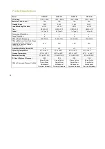
Page 22: ...ge measured with line of sight no obstacles and height of devices above floor 1m 30m 30m 30m 30m GreenWave Reality DeviceDNA v1 0 v1 0 v1 0 v1 0 Operating Temperature 0 C to 40 C 0 C to 40 C 0 C to 40...

Page 23: ...21 Document Version 1 03 Model Numbers NP220 B NP222 B NS220 B NS220 B...

Page 24: ...that interference will not occur in a particular installation If this equipment does cause harmful interference to radio or television reception which can be determined by turning the equipment off a...

Page 25: ......

Page 26: ...Back Cover...

Reviews: