background image

A d v a n c e d   Z - W a v e   T a s k s  

P o w e r N o d e s   U s e r   G u i d e  

|   1 2


Advanced Z-Wave Tasks 

This chapter is for Advanced Users only. 

The PowerNodes communicate wirelessly with the Gateway by use of Z-Wave mesh networking, which is 
a robust connection technology designed for home automation with security and privacy. The more Z-
Wave compatible devices installed in your home, the better coverage your energy management system 
will have. As a Z-Wave enabled device, the PowerNode is compatible with Z-Wave enabled networks and 
hardware from other manufacturers. 

Remove PowerNode from Network 

A PowerNode that has been previously used with a different Z-Wave network must have its association 
(homeID) with the other network removed before you can connect it to your energy management system. 
This process is called “exclusion” and requires you to perform steps with both the Gateway and the 
PowerNode. 

To complete the exclusion process, verify that your Gateway is plugged in and working, and then perform 
the following steps: 

1. 

Move the PowerNode close to the Gateway to ensure a strong radio signal. 

2. 

Plug the PowerNode into an electrical outlet. When the PowerNode is powered, its activity 
indicator turns white. 


3. 

On the


Gateway

,

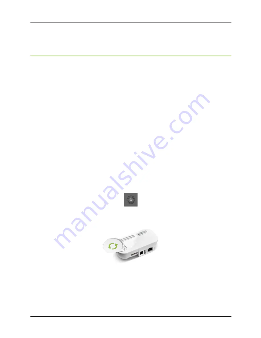
 press and hold the 

Sync

 button until the activity indicator begins to display a 

counter-clockwise rotating pattern.  


The Gateway is ready to perform the exclusion of the PowerNode. 

4. 

On the PowerNode, press and hold the 

Sync

 button for approximately one second until the 

PowerNode activity indicator begins to display a counter-clockwise rotating pattern. The 
PowerNode is attempting exclusion. 

Summary of Contents for Multi-Port PowerNode

Page 1: ...P o w e r N o d e s U s e r G u i d e i PowerNodes User Guide...

Page 2: ...Devices to the PowerNode 8 Step 5 Add Connected Devices to Your Online Account 8 Managing PowerNodes 10 Add or Change Devices Connected to PowerNode 10 Move PowerNode to a Different Room or Change the...

Page 3: ...tely through a Web browser or smart device application PowerNodes are available with a one port or multi port configuration PowerNodes automatically connect to your Gateway enabling the Gateway to sec...

Page 4: ...owerNode Port Outlet where you plug your device Room Color Selector Specifies the room color associated with the PowerNode Reset Button Resets the PowerNode to factory default settings Activity Indica...

Page 5: ...erNode Ports Outlets where you plug your devices Room Color Selector Specifies the room color associated with the PowerNode Activity Indicator and Power Button Displays status of the connection to the...

Page 6: ...t of range You can move the PowerNode closer to the Gateway or add additional PowerNodes closer to the Gateway The PowerNodes can piggyback on each other s network connection Two green bars rotating c...

Page 7: ...loss of power such as a PowerNode being powered off may cause temporary or permanent damage to such devices We recommend you refer to the manufacturer s instructions before deciding if and how to use...

Page 8: ...nt rooms to various colors making those rooms easy to identify when managing your power sources If you use more than one PowerNode in the same room you can set them to the same color Then when you acc...

Page 9: ...strong radio signal If you will be syncing more than one PowerNode start with the PowerNode that will be located closest to the Gateway when the devices are plugged in That way its wireless connection...

Page 10: ...to move it the PowerNode remains synced to the Gateway Step 4 Add Devices to the PowerNode You can add your devices to the PowerNode then add the devices to your online account If you are installing m...

Page 11: ...can also access online help for additional information and instructions on working with the Web application 2 Click the My Settings menu 3 When the Settings page opens click the Set Up Wizard option i...

Page 12: ...u 3 On the carousel select the room card and then click the room icon for the room containing the PowerNode 4 Click the icon for the port where you plugged in the new device If you are replacing an ol...

Page 13: ...improve reception When you move a PowerNode you must have the Gateway re establish its radio signals with the PowerNodes on your energy management system Re establish the Gateway s Radio Signal When...

Page 14: ...the other network removed before you can connect it to your energy management system This process is called exclusion and requires you to perform steps with both the Gateway and the PowerNode To compl...

Page 15: ...teway is not in exclusion mode and you must repeat step 3 After a few seconds the rotating pattern on both the PowerNode and the Gateway stops and all bars turn green forming a circle for several seco...

Page 16: ...ause interference with the radio signals If the Gateway is positioned vertically such as attached to the wall the radio signal strength could be reduced If the Gateway is behind a metal object the rad...

Page 17: ...e affixed label indicates that you must not discard this electrical electronic product in domestic household waste WEEE Product Category With reference to the equipment types in the WEEE Directive Ann...

Page 18: ...as irons space heaters and power tools should never be left unattended and should never be left in the on position unless you are actively using the device Hazardous if power is interrupted Certain de...

Page 19: ...ild deploy and manage connected appliances and services that both improve efficiency and enhance productivity Learn more about GreenWave at www GreenWaveReality com or follow us on Twitter at GrnWaveR...

Page 20: ...ght DeviceDNA v1 0 Power For power levels in specific regions refer to the Specifications by Region section Power Rated 120V 240V 50 60Hz Maximum Load Current 15A Standby Power 1W Load Monitoring Prec...

Page 21: ...6 port NP24x I 6 port NP21x KF 6 port NP31x F 5 port NP21x G 6 port NP22x B Socket Type Type I TypeC and K Type F Type G Type B Plug Type AS NZS 3112 CEE 7 17 and CEE7 7 DIN49441 BS1363 1 NEMA 5 15P V...

Page 22: ...or relocate the receiving antenna Increase the separation between the equipment and receiver Connect the equipment into an outlet on a circuit different from that to which the receiver is connected Co...

Reviews: