background image

– 34 –

T R A D I T I O N A L ฀ S E R I E S ฀ S T R A I G H T ฀ L E A N ฀ T O ฀ M O D E L ฀ • ฀ G R E E N H O u S E ฀ I N S T R u c T I O N S

Vent Opener

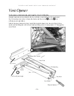
INSTALLING THE BAYLISS AUTOMATIC VENT OPENERS

Detailed instructions are included in the box with the control (there are a few extra parts).  
Use #10 stainless steel screws to fasten the Bayliss and the vent sill 

1

 and the 

2

vent

All holes are already drilled.

After the Bayliss is fastened in place, install the threaded adjuster into the swivel block. This is 
made easier by lifting the vent with one hand until the piston rod only projects 1/2” through the 
swivel block.

Power Tube

Closing Spring

Piston Rod

Arm

Sill T 

Bracket

Vent Frame Bottom Angle

Vent Gutter

Bottom Rail T Bracket

Vent

Swivel Block

Threaded Adjuster

1

2

Summary of Contents for Traditional Straight Lean To

Page 1: ...Telephone 604 882 8408 Fax 604 882 8491 Toll Free in North America 1 888 391 4433 Web Site www bcgreenhouses com Email inquiries bcgreenhouses com Traditional Series StraightLeanTo Model TLT612SG GREE...

Page 2: ...5 Glass Bar With Sliders 1 or 2 16 6 Vent Frame Angle 16 7 Glass Bars 16 Taping Glass Bars with Foam 17 8 Fastening The Base Sill To The Foundation 17 9 Side Vents Intake Shutter and Exhaust Fan Inst...

Page 3: ...ed video and follow the steps in this manual for your greenhouse installation Remember if all else fails read the instructions User Notes The Traditional greenhouse structure has been designed to with...

Page 4: ...View Picture 11 Sidewall Inside View 15 Assembly Outline Steps 1 3 16 Steps 4 7 17 Steps 8 12 18 Door Installation 31 Vent Assembly Exploded View 34 Vent Detail 35 Truss Assembly Appendix A Intake Sh...

Page 5: ...it 15 64 aluminum bit fastening perlins to trusses larger greenhouses 7 16 wrench Razor blade cutter Caulking gun Ladder Hammer Optional Automatic Opener Circulating Fan Max Min Thermometer Benches Ey...

Page 6: ...tled and moved to another location A SQUARE AND LEVEL FOUNDATION Check the width and length of the foundation s outside dimensions Then square the foundation by measuring diagonally from opposite corn...

Page 7: ...steel weather flashing a rubber or foam weather membrane or a row of weather resistant non treated wood such as cedar or hemlock 2 Other weather resistant non treated woods are popular alternatives t...

Page 8: ...T R A D I T I O N A L S E R I E S S T R A I G H T L E A N T O M O D E L G R E E N H O u S E I N S T R u c T I O N S 7...

Page 9: ...I O N A L S E R I E S S T R A I G H T L E A N T O M O D E L G R E E N H O u S E I N S T R u c T I O N S Back Gable End Line Drawing Assembly Procedure 1 2 3 4 5 8 Base Corner Post Glass Bars Back Bra...

Page 10: ...h the slot punches out facing up See Pic A and Sketch 1 page 8 2 Bolt the corner post onto the base angle See Pic B and Sketch 2 page 8 3 Bolt on all the end bars to the base Make sure that the longes...

Page 11: ...G R E E N H O u S E I N S T R u c T I O N S Front Gable End with door Line Drawing Assembly Procedure 1 2 3 4 5 7 6 10 Base Corner Post End Rafter Glass Bar Door Frame Door Frame Header Plates 4 hole...

Page 12: ...11 T R A D I T I O N A L S E R I E S S T R A I G H T L E A N T O M O D E L G R E E N H O u S E I N S T R u c T I O N S...

Page 13: ...he bottom plates 4 holes to the base sill and the doorframe sides using 1 4 x 1 2 stainless steel bolts see Picture A B and Sketch 1 page 10 Before tighten ing the bolts be sure that it is square If y...

Page 14: ...door 493 4 long can now be bolted on The 1 4 round holes should be lined up with the holes in the plates See Picture F Each end of the 1 x 2 angle has a slot punched out to accommodate the bolt that...

Page 15: ...T R A D I T I O N A L S E R I E S S T R A I G H T L E A N T O M O D E L G R E E N H O u S E I N S T R u c T I O N S Door Frame Assembly...

Page 16: ...with end Glass Bars Slide the bolts in the top of the Glass Bar before you put on the end rafter 6 At this point you can install all the end Glass Bars A smaller greenhouse will only have 1 bar above...

Page 17: ...ure E Corner post will be fastened to the ends when the greenhouse is assembled 2 Bolt the Glass Bars to the base A B Sidewall Assembly C D E Lay out the sidewall with the gutter at the top base at th...

Page 18: ...tand up side wall Slide the gutter sidewall in between the end rafter and the corner post There should be a 1 8 space see Picture A By sliding the gutter in as far as it goes the punched out slots lin...

Page 19: ...om moving round See Picture E 5 GLASS BAR WITH VENT SLIDERS See Page 21 Each Glass Bar has a small vent frame slider on it They are marked 1 2 3 4 etc On the ridge there will be the same markings Slid...

Page 20: ...wall is not plumb You may have to decide to pull the greenhouse away from the wall or make your foundation off level When your greenhouse is squared up mark the edge of the ridge on your wall and pull...

Page 21: ...19 T R A D I T I O N A L S E R I E S S T R A I G H T L E A N T O M O D E L G R E E N H O u S E I N S T R u c T I O N S 19 Assembly Outline Step 1 Back Gable End Step 2 Side Wall Step 3 Front Gable End...

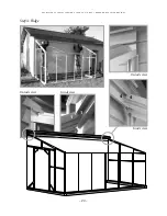
Page 22: ...T R A D I T I O N A L S E R I E S S T R A I G H T L E A N T O M O D E L G R E E N H O u S E I N S T R u c T I O N S 20 Step 4 Ridge Inside view Outside view Outside view Inside view 1 1 4 4...

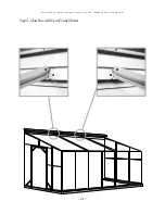
Page 23: ...T R A D I T I O N A L S E R I E S S T R A I G H T L E A N T O M O D E L G R E E N H O u S E I N S T R u c T I O N S 21 Step 5 Glass Bar with Vent Frame Sliders 3 3 2 2...

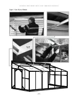
Page 24: ...22 T R A D I T I O N A L S E R I E S S T R A I G H T L E A N T O M O D E L G R E E N H O u S E I N S T R u c T I O N S Step 6 Vent Frame Bottom Inside View...

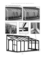
Page 25: ...23 T R A D I T I O N A L S E R I E S S T R A I G H T L E A N T O M O D E L G R E E N H O u S E I N S T R u c T I O N S Step 7 Install All Remaining Glass Bars...

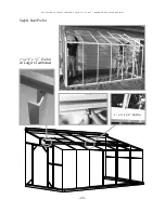
Page 26: ...24 T R A D I T I O N A L S E R I E S S T R A I G H T L E A N T O M O D E L G R E E N H O u S E I N S T R u c T I O N S Step 8 Roof Purlin 11 2 x 3 x 3 16 Purlin on Larger Greenhouses 1 x 3 x 1 8 Purli...

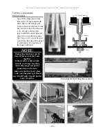
Page 27: ...um is dry Slowly roll down the tape toward the outer edge and press it down at the same time See Pictures Be careful because sometimes the edge of the paper is quite sharp Do not remove the paper unti...

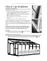
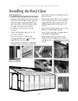
Page 28: ...t Position glass in between the inside edges of the bars Glass comes packaged in cardboard cases When storing glass put it upright against a wall or post All glass is a 3mm 24 oz thickness unless it i...

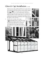
Page 29: ...Hold the cap against the glass and put in your screws When the screw hits the cap make a 1 4 turn In other words do not tighten the screws too tightly Also do not put a screw in the top hole of the c...

Page 30: ...than the glass Put in the second row of Roof Glass overlapping the first 1 2 Settle the glass agaist the cap See Picture A The second row of caps are 1 longer than the glass When you put them on the f...

Page 31: ...h succeeding row has the same size glass as per sketch but they overlap the previous row by 1 2 and are held in place by an Aluminum Cap see Side Glazing Do not caulk the bottom where the glass rests...

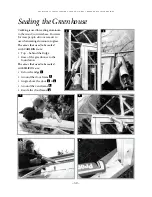
Page 32: ...num to the wood concrete base However for most people silicone is easier to use when sealing aluminum to glass The areas that need to be sealed with CAULKING are Top behind the Ridge Base of the green...

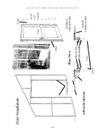
Page 33: ...p plates and move the frame to make it square When it is in place tighten all the bolts Next install the door handle see the instructions inside the box To install the door catch angle slide in two bo...

Page 34: ...G H T L E A N T O M O D E L G R E E N H O u S E I N S T R u c T I O N S Door Installation ATTACH DOOR Plan View Vertical Jamb Base Base Base Door Vertical Jamb Plate Base INSIDE GREENHOUSE OUTSIDE GR...

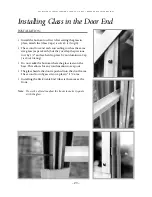
Page 35: ...rn it over and square it up 6 Put the 1 8 foam on the Glass bars and Gutter 7 Take the glass and slide it up into the hinge track Drop it down on the gutter Do the same with the next piece of glass 8...

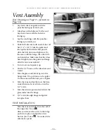
Page 36: ...0 stainless steel screws to fasten the Bayliss and the vent sill 1 and the 2 vent All holes are already drilled After the Bayliss is fastened in place install the threaded adjuster into the swivel blo...

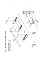
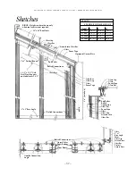
Page 37: ...E S S T R A I G H T L E A N T O M O D E L G R E E N H O u S E I N S T R u c T I O N S 35 T R A D I T I O N A L S E R I E S S T R A I G H T L E A N T O M O D E L G R E E N H O u S E I N S T R u c T I...

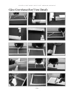
Page 38: ...Glass Greenhouse Roof Vent Details 36 T R A D I T I O N A L S E R I E S S T R A I G H T L E A N T O M O D E L G R E E N H O u S E I N S T R u c T I O N S...

Page 39: ...fter Glass Bar Glass Cap Glass Foam Tape Glass Cap Glass Foam Tape Glass Bar End Rafter Bolted Connection Glass Bar Foam Tape Glass Glass Cap Screwed into Glass Bar Glass 2 x 1 Base Angle Foam Glass C...

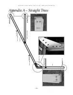
Page 40: ...dix A Straight Truss Cleated for securing to Side Glazing Bars Post Cleated for securing to Foundation Collar Tie If Applicable Cleated for securing to Existing building Cleated for securing to Existi...

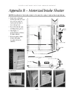
Page 41: ...1 4 x 1 2 S S Bolt Inside Inside Louvre Motor Louvre Motor Louvre Motor Rip Flush Vertical Glazing Poly Bar 241 2 Vertical Glazing Poly Bar Electric Power 26 2 x 1 x 1 8 Aluminum Angle 25 5 8 Slide bo...

Page 42: ...le and tighten Seal around shutter on outside 40 T R A D I T I O N A L S E R I E S S T R A I G H T L E A N T O M O D E L G R E E N H O u S E I N S T R u c T I O N S Appendix C Exhaust Fans 1 4 x 1 2 S...

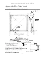
Page 43: ...oly Bar 241 2 2 x 1 x 1 8 Aluminum Angle Locking Handle GLASS POLYCARBONATE GLASS POLYCARBONATE Locking Handle 1 4 x 1 2 S S Bolt Inside 1 Slide slider on inside foam track of glass poly bar where sid...

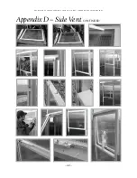
Page 44: ...42 T R A D I T I O N A L S E R I E S S T R A I G H T L E A N T O M O D E L G R E E N H O u S E I N S T R u c T I O N S Appendix D Side Vent CONTINUED...

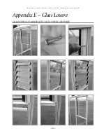
Page 45: ...43 T R A D I T I O N A L S E R I E S S T R A I G H T L E A N T O M O D E L G R E E N H O u S E I N S T R u c T I O N S Appendix E Glass Louvre GLASS OR POLYCARBONATE GLASS LOUVRE ASSEMBLY...

Page 46: ...ROOF POLYCARBONATE PANEL INSTALLATION NOTE When you install the roof panels start on the far side of the roof vent opening Work towards the vent opening When installing the last pieces in the roof you...

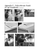
Page 47: ...45 T R A D I T I O N A L S E R I E S S T R A I G H T L E A N T O M O D E L G R E E N H O u S E I N S T R u c T I O N S Appendix F Polycarbonate Panels Cap Installation CONTINUED 4 5 6 7 1 2 3...

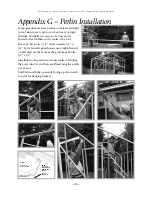
Page 48: ...Heavy perlin at least 1 4 thick requires 1 4 x 3 4 bolts Smaller greenhouses use a light channel bolts used are the same as the greenhouse bolts 1 4 x 1 2 Installation of a perlin is a simple matter o...

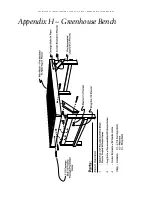
Page 49: ...47 T R A D I T I O N A L S E R I E S S T R A I G H T L E A N T O M O D E L G R E E N H O u S E I N S T R u c T I O N S Appendix H Greenhouse Bench...

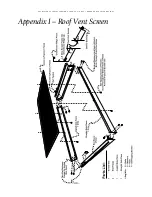
Page 50: ...Appendix I Roof Vent Screen 48 T R A D I T I O N A L S E R I E S S T R A I G H T L E A N T O M O D E L G R E E N H O u S E I N S T R u c T I O N S...

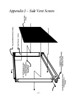
Page 51: ...49 T R A D I T I O N A L S E R I E S S T R A I G H T L E A N T O M O D E L G R E E N H O u S E I N S T R u c T I O N S Appendix J Side Vent Screen...

Page 52: ...Wire Shelving Plastic Cup Wire Shelving Front View Plastic Clip Vertical Glazing Bar Vertical Glazing Bar Vertical Glazing Bar Shelving Bracket Plastic Clip Shelving Bracket Front View 50 T R A D I T...

Page 53: ...51 T R A D I T I O N A L S E R I E S S T R A I G H T L E A N T O M O D E L G R E E N H O u S E I N S T R u c T I O N S Miscellaneous Assembly Details 1...

Page 54: ...52 T R A D I T I O N A L S E R I E S S T R A I G H T L E A N T O M O D E L G R E E N H O u S E I N S T R u c T I O N S Miscellaneous Assembly Details 2...

Page 55: ...S E I N S T R u c T I O N S T R A D I T I O N A L S E R I E S S T R A I G H T L E A N T O M O D E L G R E E N H O u S E I N S T R u c T I O N S At this point stand back and enjoy your workmanship You...

Reviews: