background image

p. 

11/48


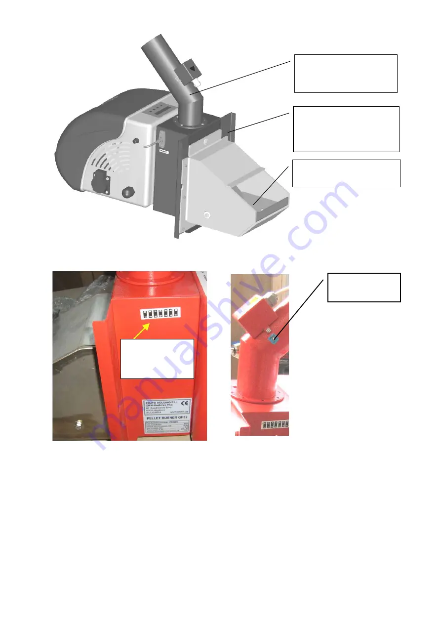
Figure 3.3

 Side view of the main unit of the pellet burner of series “GP IV”; 


Figure 3.4.

 View of the side of the burner with attached liquid crystal thermo sticker; 


COMMENTS

 : 


Reversible  liquid  crystal  thermo  sticker 

indicates  the  operating  temperature  of  the 

spot around the sticker. This temperature is indicative for the operating mode of the 
pellet burner and the hydraulic losses of the flue gases, passing through the heating 
appliance to the flue stack. The initial condition of the thermo-sticker is indicated with 
black color of  all thermo active segments. In case of temperature rise, the segments 
are  sequentially  getting  light  colored,  according  to  the  temperature  range  of  any 
individual thermo-active segments. However, the increased temperature in this zone of 
the burner is indicator for the requirement for planning of ash cleaning procedure of 
the  heating  appliance  and/or  the  chimney.  At  cooling  down  the  main  body  of  the 
burner, the reversible sticker gets into its initial condition (all segments are dark)

Fuel delivery pipe and 

“back fire” safety 

thermo-probe 

Grate of the combustion 

chamber 

Installation flange for 

attaching the main module 

to a consumer unit 

Reversible 

luquid crystal 

sticker 


Irreversible 

thermo sticker 

Summary of Contents for GP 25 IV

Page 1: ...MANUAL for installation and operation of automatic pellet burner of series GP IV http www greenecotherm eu...

Page 2: ...R PERSONAL SECURITY IT IS NECESSARY TO READ THOROUGHLY AND CAREFULLY THIS INSTRUCTION MANUAL BEFORE PROCEEDING WITH ANY ACTIONS WITH THE BURNER INSTALLATING CONNECTING OPERATING ETC IN CASE THAT REQUI...

Page 3: ...5 2 8 1 Operating mode of the burner of series GP IV 28 5 2 8 2 User menu items of the control module of pellet burner of series GP IV 29 5 2 9 User menu items in control module of automatic pellet bu...

Page 4: ...0 Other solid biomass based pellets but these fuels need testing and approval in pellet burner producer company laboratory The unit is equipped with microprocessor module which controls the functions...

Page 5: ...gy based on organized combustion process of renewable energy source biomass is less influenced by the global trend of the energy sources and as result the price is competitive compared to price of the...

Page 6: ...et burner producer classification methodology A AB B Wood pellets fuel consumption rate at nominal thermal capacity kg h 5 3 6 8 Fresh air flow rate required for effective combustion process and boile...

Page 7: ...ic value MJ kg 17 2 kWh kg 4 7 Class of wood pellets ENplus ENplus A1 Wood pellets category A AB B Ash content See Table 2 4 Moisture content Max 8 10 Table 2 3 Recommended solid biomass fuel properti...

Page 8: ...us and the generally the quality of the pellets is lower Parameter Dimension ENplus A1 ENplus A2 Diameter mm 6 1 6 1 Length mm 3 15 L 40 1 3 15 L 40 1 Bulk density kg m 600 600 Calorific value MJ kg 1...

Page 9: ...s LCD display and integrated keyboard used to change the values of the operating parameters as well as adjustment of the thermal capacity of the burner Transport auger connector which realizes power s...

Page 10: ...n unit of the pellet burner of series GP IV are shown on figure 3 2 and figure 3 3 Figure 3 2 Section view of the elements of the main unit of the burner of series GP IV Main unit Fuel transport auger...

Page 11: ...with black color of all thermo active segments In case of temperature rise the segments are sequentially getting light colored according to the temperature range of any individual thermo active segmen...

Page 12: ...than after the defined number of ignition trials the burner will go out in stop mode and alarm is indicated as well The flexible hose which connects the fuel transport auger with the main unit is tran...

Page 13: ...FF and back ON the main power supply of the burner o Reversible liquid crystal thermo sticker which shows the operating temperature in the zone around the sticker considered as characteristic for the...

Page 14: ...pliance ATTENTION the mounting of the main module of the pellet burner of series GP to a heating appliance in most of the cases hot water boiler is made by screws and corresponding nuts It is necessar...

Page 15: ...ries GP IV side views Figures 4 2 4 3 and 4 4 show the overall and detailed dimensions of the main unit of the burner which should be considered at preparing a project and installation of the applianc...

Page 16: ...4 3 Overall and characteristic dimensions of the main unit of the pellet burner of series GP IV top view Figure 4 4 Overall and characteristic dimensions of the main unit of pellet burner of series GP...

Page 17: ...t auger should be positioned in the lowest part of the hoper in order to ensure reliable fuel charging of the auger s pipe entrance The final position of the transport auger should be fixed The fuel t...

Page 18: ...eries GP 4 5 Information considering the installation of the automatic pellet burner of series GP and its operation with hot water boilers The automatic pellet burner of series GP is a separate module...

Page 19: ...ditional elements like flanges transition kits etc which allow efficient operation of the burner and the system in general thus increasing the reliability as well In ANNEX 1 of this user manual is sho...

Page 20: ...within the following range 5 20 Pa The incompleteness of this requirement could lead to alarm modes of the burner and or ineffective operation regime of the burner The operating pressure in the combu...

Page 21: ...e performed by authorized technician only The burner should be connected to the power supply of the unit at which it is attached and the appropriate safety rules should be satisfied Use the attached t...

Page 22: ...unit ATTENTION the control board of the burner monitors the presence and adequate operation of the transport auger and if the auger is not plugged in the main unit of the burner then the control board...

Page 23: ...rner ATTENTION The choice of the maximal thermal capacity stage 5th is not recommended this stage is available in order to utilize relatively low calorific value fuel or temporary demand of increased...

Page 24: ...mbustion ash cleaning procedure is activated if the option for such procedure has been activated parameter Makc comb time This parameter is in the Advance menu restricted for authorized technicians on...

Page 25: ...ent operating mode of the control module in the case the control module performs functional check procedure of the air supply fan COMMENTS TEST BLOWING indicates the operating mode in the example the...

Page 26: ...ty stage however is adjusted to allow higher thermal capacity of the burner than the nominal one this stage is dedicated for cases of low quality fuel i e with lower than required net calorific value...

Page 27: ...assword and is accessible by authorized technician only o Then the auger will operate continuously for a predefined period of 6 minutes The collected in the container fuel quantity should be weighted...

Page 28: ...case the air flow rate exceeds the optimal operating range this causes combustion chamber cooling and overall system efficiency as well The above shows that free access of the ambient air to the pell...

Page 29: ...98 indicates the intensity of the flame measured by the photosensor 5 2 8 2 User menu items of the control module of pellet burner of series GP IV At pressing and holding the S button the control mod...

Page 30: ...al capacity of the pellet burner of series GP IV according to their specific model NOTE It is highly recommended to exploit the pellet burner of series GP IV at thermal capacity stage not exceeding th...

Page 31: ...sing the thermal capacity operating set stage which results in reduced thermal capacity of the burner as well as lowered fuel consumption rate 5 3 2 Increasing the thermal capacity of the pellet burne...

Page 32: ...ollowing the applied electrical schemes to switch ON and run the operation of the burner and respectively to switch the unit OFF and stop its process At switching OFF the burner s operation its contro...

Page 33: ...ction then one should press the ESC button found below the NO label found below In case that the burner will not operate for a relatively long period of time it is recommended to shut down the central...

Page 34: ...After the burner has been cooled down to ambient temperature it should be switched off by turning off the main power supply of the heat consumer unit It is recommended to clean the deposited ash thoro...

Page 35: ...e operation of the pellet burner of series GP IV In order to check the last logged errors got at the operation of the pellet burner one should enter the LOG menu item NOTE in the LOG menu item are sho...

Page 36: ...urner and the entire system as well as the flue gases duct Figure 5 14 View of the reversible thermosticker used to measure the spot temperature initial condition at normal room temperature Figure 5 1...

Page 37: ...te maintenance service actions prior to start the burner again This thermosticker should be changed after the successful operation of the burner has been achieved the check and service of the burner i...

Page 38: ...les which conduct the air though the grate which will allow efficient combustion process and optimal air cooling of the grate After thorough cleaning of the ash residue out of the burner s grate as we...

Page 39: ...gs touch the bottom of the burner s combustion chamber 2 slide the grate until it fits below the inclined grate of the burner and there is no gap between the grate and the inclined detail of the burne...

Page 40: ...char has been incinerated and the burner cooled down After the combustion chamber has been cooled down remove the grate and clean the ash residue thoroughly Use protective gloves and appropriate instr...

Page 41: ...llows Cauterization risks caused by high temperatures as a result of the combustion process in the combustion chamber at manual cleaning processes of the surfaces of the burner i e its combustion cham...

Page 42: ...o check the condition of the flue stack as well as the heating appliance it is recommended to stop the burner and clean the ash deposits thoroughly In some situation adjustment of the operating parame...

Page 43: ...The burner does not run and start signal is present Check if the control board is in alarm mode see following table with operating and alarm indication Safety fuses are broken due to emergency short...

Page 44: ...ure of the burner It is required to clean the external surface of the photosensor or eventually to replace it It is obligatory to follow the stopping procedure described in this manual 17 Presence of...

Page 45: ...for fuel available in the hopper and the auger charged Ask for help an authorized technician 2 11 Flame process loosed at operation of the burner Ask for help an authorized technician 3 12 Error at op...

Page 46: ...TEMP SENSOR LOW Temperature sensor disconnection Check the connection of the NTC sensor 5 PHOTOSENS Problems at photosensor operation Check the condition of the photosensor replace if necessary this p...

Page 47: ...pellet burner of series GP IV The factory default settings is NTC sensor for measuring and control the burner s operation by the circulating water temperature Figure 6 1 Principal electrical scheme of...

Page 48: ...not organized by the producer Failures caused by natural disasters Earth quakes fires floods etc Unsatisfied installation maintenance and service requirements which are described in this manual Repair...

Reviews: