GREAT PLANES Venus 40arf Instruction Manual Download Page 25

❏ 

13. Make sure any servo extension cords you may have

used do not interfere with other systems (servo
arms, pushrods, etc.).

❏ 

14. Secure the pressure tap (if used) to the muffler with

high temp RTV silicone, thread locking compound
or J.B. Weld.

❏ 

15. Make sure the fuel lines are connected and are not

kinked.

❏ 

16. Balance your propeller (and spare propellers).

❏ 

17. Tighten the propeller nut and spinner.

❏ 

18. Place your name, address, AMA number and

telephone number on or inside your model.

❏ 

19. Cycle your receiver battery pack (if necessary) and

make sure it is fully charged.

❏ 

20. If you wish to photograph your model, do so before

your first flight.

❏ 

21. Remember to range check your radio when you get

to the flying field.

The Great Planes Venus 40 ARF is a great-flying model that
flies smoothly and predictably. The Great Planes Venus 40
ARF does not, however, possess the self-recovery
characteristics of a primary R/C trainer and should be flown
only by experienced R/C pilots.

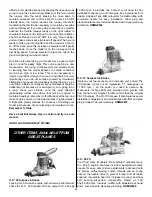
A fully cowled engine may run at a higher temperature than
an un-cowled engine. For this reason, the fuel mixture
should be richened so the engine runs at about 200 rpm
below peak speed. By running the engine slightly rich, you
will help prevent dead-stick landings caused by
overheating.

Before you get ready to takeoff, see how the model handles
on the ground by doing a few practice takeoff runs at low
speeds 
on the runway. Hold “up” elevator to keep the tail
wheel on the ground. If necessary, adjust the tail wheel so
the model will roll straight down the runway. If you need to calm
your nerves before the maiden flight, shut the engine down
and bring the model back into the pits. Top off the fuel, then
check all fasteners and control linkages for peace of mind.

Remember to takeoff into the wind. When you’re ready,
point the model straight down the runway, hold a bit of up
elevator to keep the tail on the ground to maintain tail wheel
steering, and then gradually advance the throttle. As the
model gains speed decrease up elevator allowing the tail to
come off the ground. One of the most important things to
remember with a tail dragger is to always be ready to apply
right rudder to counteract engine torque. Gain as much
speed as your runway and flying site will practically allow
before gently applying up elevator, lifting the model into the
air. At this moment it is likely that you will need to apply
more right rudder to counteract engine torque. Be smooth
on the elevator stick, allowing the model to establish a gentle
climb to a safe altitude before turning into the traffic pattern.

For reassurance and to keep an eye on other traffic, it is a
good idea to have an assistant on the flight line with you. Tell
him to remind you to throttle back once the plane gets to a
comfortable altitude. While full throttle is usually desirable
for takeoff, most models fly more smoothly at reduced speeds.

Take it easy with the Great Planes Venus 40 ARF for the
first few flights, gradually getting acquainted with it as you
gain confidence. Adjust the trims to maintain straight and
level flight. After flying around for a while, and while still at a
safe altitude with plenty of fuel, practice slow flight and
execute practice landing approaches by reducing the
throttle to see how the model handles at slower speeds.
Add power to see how she climbs as well. Continue to fly
around, executing various maneuvers and making mental
notes (or having your assistant write them down) of what
trim or C.G. changes may be required to fine tune the model
so it flies the way you like. Mind your fuel level, but use this
first flight to become familiar with your model before landing.
The Great Planes Venus 40 ARF is a very neutrally stable
airplane. It was designed as a pattern trainer and it likes
doing maneuvers large and smoothly. This is the area it
excels in and you should take advantage of that.

To initiate a landing approach, lower the throttle while on the
downwind leg. Allow the nose of the model to pitch
downward to gradually lose altitude. Continue to lose

Landing

Flight

Takeoff

CAUTION (THIS APPLIES TO ALL R/C AIRPLANES): If,
while flying, you notice any unusual sounds, such as a
low-pitched  “buzz,” this may indicate control surface
flutter. Because flutter can quickly destroy components of
your airplane, any time you detect flutter you must
immediately cut the throttle and land the airplane! Check
all servo grommets for deterioration (this may indicate
which surface fluttered), and make sure all pushrod
linkages are secure and free of play. If the control surface
fluttered once, it probably will flutter again under similar
circumstances unless you can eliminate the free-play or
flexing in the linkages. Here are some things which can
cause flutter: Excessive hinge gap; Not mounting control
horns solidly; Poor fit of clevis pin in horn; Side-play of
pushrod in guide tube caused by tight bends; Poor fit of
Z-bend in servo arm; Insufficient glue used when gluing
in the elevator joiner wire; Excessive 

play or backlash in

servo gears; and insecure servo mounting.

Fuel Mixture Adjustments

FLYING

25

Summary of Contents for Venus 40arf

Page 1: ...using the user assembled product the user accepts all resulting liability If the buyer is not prepared to accept the liability associated with the use of this product the buyer is advised to return th...

Page 2: ...lanes Venus 40 ARF visit the web site listed below and select the Great Planes Venus 40 ARF If there is new technical information or changes to this model a tech notice box will appear in the upper le...

Page 3: ...eed 4 channel radio with five servos two aileron servos Y harness for dual aileron servos HCAM2500 for Futaba J If you plan to use a computer radio you will also need 5 channel radio with five servos...

Page 4: ...r the best fit Whenever the term glue is written you should rely upon your experience to decide what type of glue to use When a specific type of adhesive works best for that step the instructions will...

Page 5: ...ets If you need assistance locating a dealer to purchase parts visit www greatplanes com and click on Where to Buy If this kit is missing parts contact Great Planes Product Support Replacement Parts L...

Page 6: ...6 x 12 Threaded On One End Pushrods 6 2 56 Nylon Clevises 6 Silicone Retainers 4 FasLinks 1 Brass EZ Connector 1 4 40 x 1 4 Socket Head Cap Screw 1 Nylon EZ Retainer 2 5 32 Wheel Collars 2 6 32 x 1 4...

Page 7: ...and the leading edge of the aileron Drill a 3 32 2 4mm hole 1 2 12mm deep in the center of each hinge slot to allow the CA to wick in Follow up with a 11 blade to clean out the slots Hint If you have...

Page 8: ...the opening if necessary Mark the location of the servo mounting screws and drill 1 16 1 6mm holes at the marks Wick some thin CA in the holes you just made and install the aileron servo with the hard...

Page 9: ...take as much time as necessary to glue the two wings together correctly Epoxy should be used generously in each one of the following steps Use 30 minute epoxy to allow enough time to fit the parts and...

Page 10: ...way the MonoKote on the top and bottom of the wing and seal with a sealing iron 3 Test fit the wing to the fuse and bolt it in position using two 1 4 20 x 2 51mm nylon bolts If necessary enlarge or ad...

Page 11: ...pan under the wing and mark its edges on the wing with a Top Flite Panel Line Pen Hint If you tape the belly pan to the fuselage for this step it will not move and it will be easier to mark both sides...

Page 12: ...s thus leaving flaps of covering that can be ironed to the stab and fin after gluing them into position 2 Fit the stab into the fuse Center the trailing edge by taking accurate measurements as shown i...

Page 13: ...fuse where the stab fits Slide the stab into position Wipe away residual epoxy with a paper towel and alcohol Use the pin and string method to confirm the stab is aligned Stand behind the model to che...

Page 14: ...4mm brass tube to cut a groove on the leading edge of the rudder to accommodate the tail wheel wire 14 Cut six CA hinges for the elevators and three for the rudder just as it was done for the ailerons...

Page 15: ...e back of the firewall Use a small amount of epoxy on the blind nuts to keep them in place Do not get epoxy in the threads 3 Find the left and right engine mounts and cut off the spreader bar on both...

Page 16: ...l Be certain you install the fuel tank inside the fuselage with the vent tube pointing up and the fill tube down Tighten the fuel tank screw 10 Glue a 1 2 x 1 4 12mm x 6 4mm balsa stick not included a...

Page 17: ...rvos Depending on the size of your servos you may have to slightly trim the tray Place the servos in the tray and mount them with the hardware that came with the servos Center the rudder servo arm If...

Page 18: ...servos and the Y harness to the receiver Glue two 1 2 x 1 4 12mm x 6 4mm balsa sticks not included to secure the battery and receiver in place 10 Make a small hole through the bottom of the fuselage...

Page 19: ...aper strips to mark the location of the needle valve engine glow plug access and muffler Remove the muffler and needle valve 6 Install the cowl with four 2 x 3 8 9 5mm screws and four 2 washers and ma...

Page 20: ...ishes the installation of the landing gear 1 Cut the instrument panel decal from the decal sheet and place it in position in the cockpit 2 If you wish to install a pilot now it is the time to do it On...

Page 21: ...ndicated in the chart that follows If your radio does not have dual rates we recommend setting the throws somewhere between the low rate and the high rate setting Note The throws are measured at the w...

Page 22: ...ly inside Note Do not rely upon the adhesive on the back of the lead weight to permanently hold it in place Over time fuel and exhaust residue may soften the adhesive and cause the weight to fall off...

Page 23: ...ly and rapidly to full power and maintains full power indefinitely After you run the engine on the model inspect the model closely to make sure all screws remained tight the hinges are secure the prop...

Page 24: ...ed helper 3 I will perform my initial turn after takeoff away from the pit or spectator areas and I will not thereafter fly over pit or spectator areas unless beyond my control 4 I will operate my mod...

Page 25: ...e elevator stick allowing the model to establish a gentle climb to a safe altitude before turning into the traffic pattern For reassurance and to keep an eye on other traffic it is a good idea to have...

Page 26: ...o maintain heading remember to throttle back at the top and make certain you are on the desired rates high low rates A flight plan greatly reduces the chances of crashing your model just because of po...

Page 27: ...hey perform predictably throughout the full rpm range Their symmetric pitch reduces prop vibration and boosts thrust at any rpm a top choice for all fliers Hobbico Accu Cycle Tx Rx Battery Cycler HCAP...

Page 28: ...Engine Spacing Template Engine Mount Template...

Reviews: