GREAT PLANES Venus 40arf Instruction Manual Download Page 14

❏ 

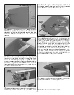
11. Position the tail wheel assembly in place and mark

the location of the two mounting holes. Drill the two holes
with a 1/16" [1.6mm] drill bit. Wick some thin CA in the holes.
Install the tail wheel assembly using two #4 x 1/2" [12mm]
screws as shown.

❏ 

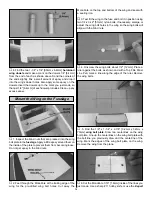
12. Position the rudder in place and mark where the tail

wire is inserted in the rudder. The bottom of the tail wheel
wire’s first coil should be 1/8" [3.2mm] away from the tail
wheel support as shown above. Use a 3/32" [2.4mm] drill bit
to drill a hole into the rudder 1-1/4" [32mm] at the mark.
Make sure the hole is perpendicular with the rudder’s
leading edge and be careful not to drill through the covering.

❏ 

13. Use a Groove Tube or a sharpened 3/32" [2.4mm]

brass tube to cut a groove on the leading edge of the rudder
to accommodate the tail wheel wire.

❏ 

14. Cut six CA hinges for the elevators and three for the

rudder just as it was done for the ailerons.

❏ 

15. Test fit the rudder on the fin with the tail wheel wire

and the CA hinges. Adjust the groove and the hole on the
leading edge of the rudder until everything fits well. Remove
the rudder from the fin. Mix a small amount of 30-minute
epoxy and wick it into the rudder’s tail wheel wire hole.
Install the rudder in position with the CA hinges just as it
was done for the ailerons on page 7, and apply six drops of
thin CA to each side of each CA hinge. Clean up any excess
epoxy with a paper towel and alcohol.

❏ 

16. Follow steps two to seven of 

“Assemble the Wing”

on page 7 to install the CA hinges on the elevator. Important:
Make sure you apply six drops of thin CA on each side of
each hinge.

14

Summary of Contents for Venus 40arf

Page 1: ...using the user assembled product the user accepts all resulting liability If the buyer is not prepared to accept the liability associated with the use of this product the buyer is advised to return th...

Page 2: ...lanes Venus 40 ARF visit the web site listed below and select the Great Planes Venus 40 ARF If there is new technical information or changes to this model a tech notice box will appear in the upper le...

Page 3: ...eed 4 channel radio with five servos two aileron servos Y harness for dual aileron servos HCAM2500 for Futaba J If you plan to use a computer radio you will also need 5 channel radio with five servos...

Page 4: ...r the best fit Whenever the term glue is written you should rely upon your experience to decide what type of glue to use When a specific type of adhesive works best for that step the instructions will...

Page 5: ...ets If you need assistance locating a dealer to purchase parts visit www greatplanes com and click on Where to Buy If this kit is missing parts contact Great Planes Product Support Replacement Parts L...

Page 6: ...6 x 12 Threaded On One End Pushrods 6 2 56 Nylon Clevises 6 Silicone Retainers 4 FasLinks 1 Brass EZ Connector 1 4 40 x 1 4 Socket Head Cap Screw 1 Nylon EZ Retainer 2 5 32 Wheel Collars 2 6 32 x 1 4...

Page 7: ...and the leading edge of the aileron Drill a 3 32 2 4mm hole 1 2 12mm deep in the center of each hinge slot to allow the CA to wick in Follow up with a 11 blade to clean out the slots Hint If you have...

Page 8: ...the opening if necessary Mark the location of the servo mounting screws and drill 1 16 1 6mm holes at the marks Wick some thin CA in the holes you just made and install the aileron servo with the hard...

Page 9: ...take as much time as necessary to glue the two wings together correctly Epoxy should be used generously in each one of the following steps Use 30 minute epoxy to allow enough time to fit the parts and...

Page 10: ...way the MonoKote on the top and bottom of the wing and seal with a sealing iron 3 Test fit the wing to the fuse and bolt it in position using two 1 4 20 x 2 51mm nylon bolts If necessary enlarge or ad...

Page 11: ...pan under the wing and mark its edges on the wing with a Top Flite Panel Line Pen Hint If you tape the belly pan to the fuselage for this step it will not move and it will be easier to mark both sides...

Page 12: ...s thus leaving flaps of covering that can be ironed to the stab and fin after gluing them into position 2 Fit the stab into the fuse Center the trailing edge by taking accurate measurements as shown i...

Page 13: ...fuse where the stab fits Slide the stab into position Wipe away residual epoxy with a paper towel and alcohol Use the pin and string method to confirm the stab is aligned Stand behind the model to che...

Page 14: ...4mm brass tube to cut a groove on the leading edge of the rudder to accommodate the tail wheel wire 14 Cut six CA hinges for the elevators and three for the rudder just as it was done for the ailerons...

Page 15: ...e back of the firewall Use a small amount of epoxy on the blind nuts to keep them in place Do not get epoxy in the threads 3 Find the left and right engine mounts and cut off the spreader bar on both...

Page 16: ...l Be certain you install the fuel tank inside the fuselage with the vent tube pointing up and the fill tube down Tighten the fuel tank screw 10 Glue a 1 2 x 1 4 12mm x 6 4mm balsa stick not included a...

Page 17: ...rvos Depending on the size of your servos you may have to slightly trim the tray Place the servos in the tray and mount them with the hardware that came with the servos Center the rudder servo arm If...

Page 18: ...servos and the Y harness to the receiver Glue two 1 2 x 1 4 12mm x 6 4mm balsa sticks not included to secure the battery and receiver in place 10 Make a small hole through the bottom of the fuselage...

Page 19: ...aper strips to mark the location of the needle valve engine glow plug access and muffler Remove the muffler and needle valve 6 Install the cowl with four 2 x 3 8 9 5mm screws and four 2 washers and ma...

Page 20: ...ishes the installation of the landing gear 1 Cut the instrument panel decal from the decal sheet and place it in position in the cockpit 2 If you wish to install a pilot now it is the time to do it On...

Page 21: ...ndicated in the chart that follows If your radio does not have dual rates we recommend setting the throws somewhere between the low rate and the high rate setting Note The throws are measured at the w...

Page 22: ...ly inside Note Do not rely upon the adhesive on the back of the lead weight to permanently hold it in place Over time fuel and exhaust residue may soften the adhesive and cause the weight to fall off...

Page 23: ...ly and rapidly to full power and maintains full power indefinitely After you run the engine on the model inspect the model closely to make sure all screws remained tight the hinges are secure the prop...

Page 24: ...ed helper 3 I will perform my initial turn after takeoff away from the pit or spectator areas and I will not thereafter fly over pit or spectator areas unless beyond my control 4 I will operate my mod...

Page 25: ...e elevator stick allowing the model to establish a gentle climb to a safe altitude before turning into the traffic pattern For reassurance and to keep an eye on other traffic it is a good idea to have...

Page 26: ...o maintain heading remember to throttle back at the top and make certain you are on the desired rates high low rates A flight plan greatly reduces the chances of crashing your model just because of po...

Page 27: ...hey perform predictably throughout the full rpm range Their symmetric pitch reduces prop vibration and boosts thrust at any rpm a top choice for all fliers Hobbico Accu Cycle Tx Rx Battery Cycler HCAP...

Page 28: ...Engine Spacing Template Engine Mount Template...

Reviews: