


INTRODUCTION ................................................................2
SAFETY PRECAUTIONS ..................................................2
ADDITIONAL ITEMS REQUIRED ....................................3
Hardware & Accessories ....................................................3
Adhesives & Building Supplies ..........................................3
Optional Supplies & Tools ..................................................3
IMPORTANT BUILDING NOTES ......................................4
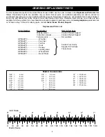
ORDERING REPLACEMENT PARTS ..............................5
METRIC CONVERSIONS ..................................................5
METRIC/INCH RULER ......................................................5
KIT CONTENTS ................................................................6
PREPARATIONS................................................................7
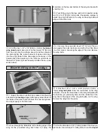
ASSEMBLE THE WING ....................................................7
Attach the Ailerons ............................................................7
Join the Wing......................................................................9
Mount the Wing on the Fuselage ....................................10
ASSEMBLE THE FUSELAGE ........................................12
Install the Tail Surfaces ....................................................12
Engine Installation ............................................................15
Radio Installation..............................................................16
Installing the Cowl ............................................................18
Installing the Landing Gear ..............................................20
Finish the Cockpit ............................................................20
Apply the Decals ..............................................................20
GET THE MODEL READY TO FLY..................................21
Check the Control Directions ..........................................21
Set the Control Throws ....................................................21
Balance the Model (C.G.) ................................................22
Balance the Model Laterally ............................................22
PREFLIGHT ....................................................................23
Identify Your Model ..........................................................23
Charge the Batteries ........................................................23
Balance the Propeller ......................................................23
Ground Check ..................................................................23
Range Check....................................................................23
ENGINE SAFETY PRECAUTIONS ................................23
AMA SAFETY CODE (excerpt) ......................................24
CHECK LIST....................................................................24
FLYING ............................................................................25
Fuel Mixture Adjustments ................................................25
Takeoff ..............................................................................25
Flight ................................................................................25
Landing ............................................................................25
ENGINE SPACING TEMPLATE ........BACK COVER PAGE
ENGINE MOUNT TEMPLATE ..........BACK COVER PAGE
The Great Planes Venus 40 ARF is a versatile airplane
designed for pattern training and sport flying. The Venus 40
ARF is neutrally stable. That means that it will stay in
whatever position you put it in as long as it has enough
flying speed. The model exhibits no roll or pitch coupling on
knife edge when the C.G. is located at the recommended
point. On low rates, this airplane likes doing large, smooth
maneuvers, which is perfect for practicing all those
precision aerobatic maneuvers. On high rates, it hovers
great and does torque rolls with a .70 4-stroke. All in all, this
airplane is a low cost approach to pattern aerobatics that
will give you many hours of fun.
For the latest technical updates or manual corrections to the
Great Planes Venus 40 ARF visit the web site listed below
and select the Great Planes Venus 40 ARF. If there is new
technical information or changes to this model a “tech
notice” box will appear in the upper left corner of the page.
http://www.greatplanes.com/airplanes/index.html
1. Your Great Planes Venus 40 ARF should not be
considered a toy, but rather a sophisticated, working model
that functions very much like a full-size airplane. Because of
its performance capabilities, the Venus 40 ARF, if not
assembled and operated correctly, could possibly cause
injury to you or spectators and damage to property.
2. You must assemble the model according to the
instructions. Do not alter or modify the model, as doing so
may result in an unsafe or unflyable model. In a few cases
the instructions may differ slightly from the photos. In those
instances the written instructions should be considered as
correct.
3. You must take time to build straight, true and strong.
4. You must use an R/C radio system that is in first-class
condition, and a correctly sized engine and components
(fuel tank, wheels, etc.) throughout the building process.
5. You must correctly install all R/C and other components
so that the model operates correctly on the ground and in
the air.
6. You must check the operation of the model before every
flight to insure that all equipment is operating and that the
model has remained structurally sound. Be sure to check
clevises or other connectors often and replace them if they
show any signs of wear or fatigue.
7. If you are not already an experienced R/C pilot, you
should fly the model only with the help of a competent,
experienced R/C pilot.
8. While this kit has been flight tested to exceed normal use,
if the plane will be used for extremely high stress flying,
such as extreme 3D flying, the modeler is responsible for
taking steps to reinforce the high stress points.
PROTECT YOUR MODEL, YOURSELF
& OTHERS...FOLLOW THESE
IMPORTANT SAFETY PRECAUTIONS
INTRODUCTION
TABLE OF CONTENTS
2