❏
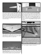
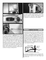
6. Located on the bottom of the fuselage are two plywood
plates. Drill a 1/16" [1.6mm] hole in the center of each of the
plates. Install a #2 x 3/8" [9.5mm] screw and a #2 washer
through the end of the wire from the left and right side of the
stab. Thread the screw into the plate. Repeat this for the
remaining wire.
❏
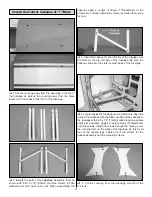
7. Proceed to loosen the set screw enough to allow the
wire to be pulled through the post. Lightly tension each wire
before re-tightening the set screw. The wires do not need to
be overly tight; snug is adequate. When you are satisfied
with the tension of the wires, cut the excess wire
approximately 1/4" [6mm] from the post. This will allow
enough wire to grab onto with pliers should you ever need to
make further adjustments.
If you are installing a brand of glow engine other than the
O.S.
®
, read through the installation instructions for the O.S.
1.60. The procedure should be similar. The most important
thing is to be sure to follow the spacing dimensions from the
engine drive washer back to the firewall
If you are installing the Fuji-IMVAC
™
BT-43 EIS or other gasoline
engine, skip ahead to the instructions for mounting that engine.
If you will be using another brand of gasoline engine, read
through the installation instructions for the Fuji-IMVAC. You
should find the mounting instructions for the Fuji-IMVAC helpful
in determining the best way to mount your particular brand of
engine. Skip to page 21 for gas engine installation.
Installation instructions for the O.S. 1.60 two-cycle engine
❏
1. On page 33 of this manual you will find the engine
mounting template for the O.S. 1.60 engine. Cut out the
template from the manual and tape it to the firewall, aligning
the lines of the template with the lines on the firewall.
❏
2. On each of the four marks drill a 7/32" [5.6mm] hole.
Install an 8-32 blind nut into each of the holes from the back
of the firewall. Install a #8 flat washer onto a 8-32 x 1"
[25mm] socket-head cap screw. Then, tighten the screw into
the blind nut, pulling it into the firewall
❏
3. Cut the tabs from the engine mount. Install the engine
mount to the firewall with four 8-32 x 1-1/4" [32mm] socket-
head cap screws, #8 flat washers and #8 lock washers.
When installing the mount, be sure that you have the mount
positioned allowing the engine to be mounted on its side.
Install the Engine
20


