The relationship between the “step” on the floats and the
center of gravity on the model is important. First, the floats
should be mounted on the model so the step is positioned
as detailed in the “Step Sketch” for your particular model.
Then, when the floats are mounted on the model, move the
C.G. slightly forward as listed below. Although you may
have added the recommended ballast inside the front of
the float, in some cases a little more ballast may be
required on the model.
For 60-size floats: Move the CG (Balance point) 1/2"
ahead of the manufacturers recommended CG.
For 40-size floats: Move the CG (Balance point) 3/8"
ahead of the manufacturers recommended CG.
For 20-size floats: Move the CG (Balance point) 9/32"
ahead of the manufacturers recommended CG.
Another important relationship between the wing and the
floats is the relative “angle of attack.’’ With a virtually flat
bottom wing such as a Piper Cub, the deck of the floats
should be parallel to the bottom of the wing. Since the Cub
does not have a truly flat wing, this yields a slight positive
wing incidence in relation to the floats, and the airplane will
tend to rise off the water at the correct time. If you have a
model with a symmetrical wing, the wing incidence in
relation to the float deck should be positive 1-1/2 degrees.
Finally, each float should be set so that it is parallel to the
centerline of the fuselage.
❏
1. You must have a solid mounting location on the
fuselage bottom for the aft float strut. If you have not
previously built in the aft float mount plate to the bottom
of your fuselage, follow the instructions below.
A. For greatest strength, it is preferred that the 1/8”
plywood aft float mount plate (included with the float
kit) be positioned under a former. The location of the aft
float mount plate is determined by the aft strut (included
with the float kit) which can be custom bent. On the
Great Planes Cub 60 and Cub 20, the location of the aft
float mount plate is shown on the plan included with the
model. To locate the former, push a pin through the
bottom of the fuselage until you find it.
B. Remove a section of the bottom sheeting, centered
over the former, wide enough to accept the aft float
mount plate.
Prepare Your Airplane to Accept
the Floats
13
Summary of Contents for Sport Floats
Page 4: ...4 DIE CUT PATTERNS 60 SIZE...
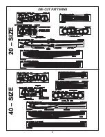
Page 5: ...5 DIE CUT PATTERNS 20 SIZE 40 SIZE...
Page 21: ......


