background image

indicated in the chart that follows. If your radio does not have
dual rates, we recommend setting the throws 

between the

high and low rate settings.

NOTE: The throws are measured at the widest part of the
elevators, rudder and ailerons.

At this stage the model should be in ready-to-fly condition
with all of the systems installed including the engine, landing
gear, covering and paint and the radio system. The fuel tank
should be empty.

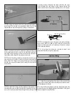
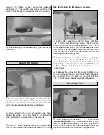
1. Use a felt-tip pen or 1/8"-wide tape to accurately mark

the C.G. on the bottom of the wing on both sides of the
fuselage. The C.G. is located 3-3/16" [81mm] back from
the leading edge of the wing where it meets the fuselage.

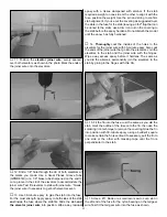
2. With the wing attached to the fuselage, all parts of the

model installed (ready to fly) and an empty fuel tank, place
the model on a Great Planes CG Machine, or lift it at the
balance point you marked.

3. When the model is lifted at the recommended balance

point it is likely that the nose will drop, thus indicating that the
model is nose-heavy and will require tail weight to balance.
However, if the tail drops, the model is tail heavy and the
model will require nose weight. If you haven't already done
so, move the battery pack and receiver to a location that will
minimize or eliminate any additional ballast required. If
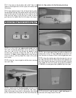
additional weight is required to balance the model, nose
weight may be easily added by using a “spinner weight”
(GPMQ4645 for the 1 oz. weight, or GPMQ4646 for the 2 oz.
weight). If spinner weight is not practical or is not enough,
use Great Planes (GPMQ4485) “stick-on” lead. A good place
to add stick-on lead to the nose is to the firewall (don't attach
weight to the cowl—it is not intended to support weight). If tail
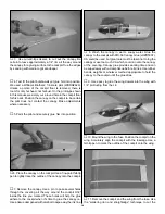
weight is required (as will most likely be the case), it may be
temporarily attached to the bottom of the stab or fuse. When
the amount of tail weight is finalized after test flying, the tail
block may be cut open and weight permanently glued inside.

Note: Do not rely upon the adhesive on the back of the lead
weight to permanently hold it in place. Over time, fuel and
exhaust residue may soften the adhesive and cause the
weight to fall off. Use RTV silicone or epoxy to permanently
hold the weight in place.

4. IMPORTANT: If you found it necessary to add any

weight, recheck the C.G. after the weight has been installed.

3-3/16"

This is where your model should balance for your first
flights. Later, you may wish to experiment by shifting the
C.G. up to 7/16" [11mm] forward or 7/16" [11mm] back to
change the flying characteristics. Moving the C.G. forward
may improve the smoothness and stability, but it may then
require more speed for takeoff and make it more difficult
to slow for landing. Moving the C.G. aft makes the model
more maneuverable, but could also cause it to become
difficult to control. In any case, start at the recommended
location and do not at any time balance the model outside
the recommended range.

BOTTOM OF WING

3-3/16"

3-3/16"

More than any other factor, the C.G. (center of gravity or
balance point) can have the greatest effect on how a
model flies and may determine whether or not your first
flight will be successful. If you value this model and wish to
enjoy it for many flights, DO NOT OVERLOOK THIS
IMPORTANT PROCEDURE. 
A model that is not properly
balanced will be unstable and possibly unflyable.

Balance the Model (C.G.)

IMPORTANT: The Shoestring ARF has been extensively
flown and tested to arrive at the throws at which it flies
best. Flying your model at these throws will provide you
with the greatest chance for successful first flights. If, after
you have become accustomed to the way the Shoestring
flies, you would like to change the throws to suit your
taste, that is fine. However, too much control throw could
make the model difficult to control, so remember, “more is
not always better.”

These are the recommend control surface throws:

High Rate

Low Rate

ELEVATOR:

3/4" [19mm] up

1/2" [13mm] up

3/4" [19mm] down

1/2" [13mm] down

RUDDER:

1-1/4" [32mm] right

3/4" [19mm] right

1-1/4" [32mm] left

3/4" [19mm] left

AILERONS:

9/16" [14mm] up

3/8" [9mm] up

9/16" [14mm] down

3/8" [9mm] down

20

Summary of Contents for Shoestring ARF

Page 1: ...uct By the act of using the user assembled product the user accepts all resulting liability If the buyer is not prepared to accept the liability associated with the use of this product the buyer is ad...

Page 2: ...home made details such as landing gear fairings and an air scoop Note The Shoestring is covered in TopFlite Red TOPQ0201 6 roll and Cub Yellow TOPQ0220 6 roll MonoKote film The full size Shoestring ha...

Page 3: ...arter scale making it eligible to fly in IMAA events The IMAA International Miniature Aircraft Association is an organization that promotes non competitive flying of giant scale models If you plan to...

Page 4: ...tional items we used to assemble the Shoestring ARF 21ST Century sealing iron COVR2700 21ST Century iron cover COVQ2702 Milled Fiberglass GPMR6165 Microballoons TOPR1090 Builders Triangle Set HCAR0480...

Page 5: ...2 Screws aileron control horns 4 2 x 3 8 Screws wheel pants 5 Silicone retainers clevises 4 8 Flat washers engine mount 1 3 32 Wheel collar tail wheel 1 4 40 Set screw tail wheel 1 Brass body screw lo...

Page 6: ...You can do one wing at a time or work on them together 1 Drill a 3 32 hole 1 2 deep in the center of each hinge slot to allow the CA to wick in Follow up with a 11 blade to clean out the slots Hint I...

Page 7: ...g the nylon control horn Before mounting the horn use a pin to poke several holes through the covering in the mounting location Saturate the holes with thin CA wipe away residual CA and allow to fully...

Page 8: ...the servo wire and the Y harness with heat shrink tubing tape or clips suitable for that purpose 1 Inspect the blind nuts that are pressed into the bottom of the wing nut plate inside the fuselage If...

Page 9: ...g a flap that can be ironed to the stab and fin after gluing them into position 2 Cut a round groove or a notch in the fuse at the TE of the stab to accommodate the elevator joiner wire 3 Fit the stab...

Page 10: ...yet 8 Remove the stab from the fuse Use a sharp 11 hobby knife or use the Expert Tip that follows to cut the covering from the stab along the lines you marked Use care to cut only into the covering a...

Page 11: ...n the fuse for the stab leaving a 3 32 flap that can be ironed to the stab use a trim iron to iron the covering to the stab before the epoxy hardens Do not disturb the model until the epoxy has fully...

Page 12: ...pant mounts 2 Glue the mounts together with the holes centered over each other 3 Holding one of the wheel pants as shown in the photo with the front of the pant toward the left insert a wheel into th...

Page 13: ...the wheel collar and set screw 12 Place the model on its gear on the workbench Prop up the tail until the fuse is level Adjust both wheel pants so they are level with the workbench 13 Without moving t...

Page 14: ...ral holes through the covering all the way around the cockpit 3 32 inside the line you marked These holes will help the glue adhere to the cockpit when it s time to glue the canopy on Use a tissue dam...

Page 15: ...8 lock washers and 8 flat washers but do not fully tighten the bolts Place the back plate of the spinner on the engine Adjust the width of the mount to fit the engine Center the molded in tick marks...

Page 16: ...l in position mark drill and mount the cowl to the remaining three cowl mounting blocks the same way Before finishing the cowl now is a good time to install the fuel tank 8 Arrange the stopper and tub...

Page 17: ...uded with this kit Use epoxy to securely glue the filler valve mount to the firewall in a location where the filler valve will be accessible outside the cowl when it s time to fuel the engine 12 Use e...

Page 18: ...ttle servo with a screw lock pushrod connecter Make a brace for the aft end of the guide tube from 1 8 leftover balsa or plywood not supplied with this kit and glue it to the former as shown in the pr...

Page 19: ...et or something similar to squeegee the rest of the water from under the decal Allow to dry overnight before flying the model 3 Apply 1 4 yellow striping tape GPMQ1450 around the base of the canopy 1...

Page 20: ...inside Note Do not rely upon the adhesive on the back of the lead weight to permanently hold it in place Over time fuel and exhaust residue may soften the adhesive and cause the weight to fall off Us...

Page 21: ...our fuel to foam which will in turn cause your engine to run hot or quit We use a Top Flite Precision Magnetic Prop Balancer TOPQ5700 in the workshop and keep a Great Planes Fingertip Prop Balancer GP...

Page 22: ...e that explodes burns or propels a projectile of any kind 1 I will have completed a successful radio equipment ground check before the first flight of a new or repaired model 2 I will not fly my model...

Page 23: ...ow speeds on the runway Hold up elevator to keep the tail wheel on the ground If necessary adjust the steering by using pliers to bend the tail gear wire so the model will roll straight down the runwa...

Page 24: ...the nose of the model to pitch downward to gradually decrease altitude Continue to lose altitude but maintain airspeed by keeping the nose down as you turn onto the crosswind leg Make the final turn t...

Reviews: