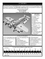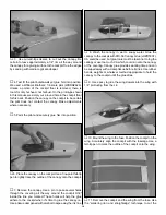
Refer to this photo while mounting the servos.
❏
3. Test fit the rudder, elevator and throttle servos in the
1/8" plywood servo tray. Make modifications to the tray if
necessary to fit the servos. Use epoxy to glue the servo tray
into the fuse.
❏
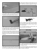
4. Place the servos in the tray. Center the elevator and
rudder. If necessary, bend the elevator and rudder pushrods
to align with the holes in the servo arms, then cut the
pushrods so they can be connected to the servos with a
nylon FasLink as shown in the sketch.
❏
5. Connect the pushrods to the servos. Drill 1/16" holes
through the servo tray for mounting the elevator and rudder
servos. Add a drop of thin CA to each hole and allow to
harden. Mount the servos to the servo tray with the screws
that came with the servos.
Hook up the throttle...
❏
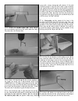
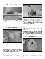
6. Drill a 3/16" hole through the firewall for the throttle
pushrod guide tube. Be certain to not drill into the tank! It
may be helpful to remove the engine for this step, so it does
not interfere with drilling the hole (or use an extended drill bit).
❏
7. Insert the 3/16" x 12" throttle pushrod guide tube
through the hole in the firewall. Bend the 17" throttle pushrod
as necessary, then connect it to the carb arm on the engine
with a nylon clevis and connect it to the throttle servo with a
screw-lock pushrod connecter. Make a brace for the aft end
of the guide tube from 1/8" leftover balsa or plywood (not
supplied with this kit) and glue it to the former as shown in
the previous photo. Mount the throttle servo to the servo tray.
❏
8. Glue the guide tube to the brace and the firewall.
❏
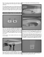
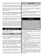
9. Wrap the battery pack and receiver in at least 1/4" of
R/C foam rubber and install them in the fuselage. On our
model with an O.S. MAX .61 FX, the battery and receiver
were mounted where shown in the photo to minimize the
amount of tail weight required to balance the model at the
correct C.G. (with a 2-stroke engine, a small amount of tail
weight may be required). Securely hold the battery pack and
receiver in position with a balsa stick glued between the fuse
sides. Simply stuffing the receiver and battery pack in place
with additional foam rubber is not a secure method of holding
them down. Note: Be certain that the wing bolts do not
dislodge the balsa stick that holds the battery and receiver in
the fuse. The wing bolts may be shortened if necessary.
❏
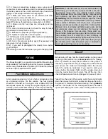
10. Mount the receiver on/off switch. A Great Planes
Switch & Charge Jack Mounting Set (GPMM1000, not
included) was used on this model. Be certain it is in a
location away from engine exhaust.
❏
11. Make certain all the servo arms are secured to the
servos with the screws that came with them and that all the
clevises have retainers on them.
FasLink
2-56 (.074") Pushrod Wire
Servo Horn
18


