background image

❏  ❏ 

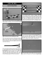
4. Reposition the axle onto the gear and tighten the

screw. Be certain that the screw has “landed” on the flat spot
and that the axle has remained parallel with the leading edge
of the wing. If not, remove the axle and adjust the flat spot as
necessary. Securely mount the axle to the landing gear with the
6-32 x 1/4" cap screw and a drop of threadlocker on the screw.

❏ ❏ 

5. Fit of the right wheel pant over the gear. (The right

wheel pant is the one that fits the right wing best when fit over
the landing gear.) Slip a wheel collar followed by a 4" wheel
and another wheel collar onto the axle. Adjust the position of
the wheel collars until the wheel is centered in the opening in
the wheel pant. Temporarily tighten the outer wheel collar to
the axle with a 6-32 set screw.

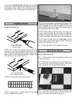
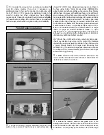
Refer to this sketch for the following two steps.

❏ ❏ 

6. With the wheel pant positioned on the wing so the

wheel is centered in the opening, drill 1/16" holes through
the wheel pant into the landing gear blocks where indicated
by the arrows in the sketch. Enlarge the holes in the wheel
pants 

only

with a 3/32" drill, then mount the pants to the

wing with four #2 x 1/2" screws.

❏ ❏ 

7. Drill 1/16" holes into the wing over the landing gear

rails for the landing gear straps. Secure the landing gear 
to the wing with four nylon landing gear straps and eight 
#2 x 1/2" screws.

❏ ❏ 

8. Now that the final position of the wheel pant, wheel

and wheel collars has been determined, remove the wheel
pant and the wheel from the landing gear. File a flat spot on
the axle for the set screw in the wheel collar that holds on
the wheel. Reassemble all the parts using a drop of
threadlocker on the set screw in the wheel collar.

❏ 

8. Return to step 1 and mount the left landing gear and

wheel pant to the wing the same way.

While working on the fuse, it helps to have a stand or a
cradle. We use a Robart Super Stand II (ROBP1402).

❏ 

1. Trim the covering from the fuse over the slots for the

stab and fin and over the holes for the rudder control cables.

❏ 

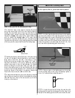
2. View the aft former through the slot for the rudder.

Check to see if there is a balsa 

hinge block

glued to the

former for the bottom rudder hinge. If there isn't one, make
a 1/4" x 1/4" x 1-1/2" (or a similar size) hinge block from a
balsa stick and glue it into position as shown in the sketch.

❏ 

3. Temporarily install the stab in the fuse. At the trailing

edge, measure the distance between the tips and the fuse.
Position the stab until both measurements are equal and the
trailing edge of the stab is centered.

1/4" x 1/4" x 1-1/2"
Balsa Hinge Block

Aft Former

Install the Stab

JOIN THE TAIL SURFACES

TO THE FUSE

Top of Wheel Pant Where

It Contacts the Wing

Landing Gear

Straps

Landing Gear

Blocks

9

Summary of Contents for Ryan STA

Page 1: ...al user assembled product By the act of using the user assembled product the user accepts all resulting liability If the buyer is not prepared to accept the liability associated with the use of this p...

Page 2: ...Ryan STA ARF rest assured Its flight performance more than lives up to its great looks This model is definitely one of the most gentle honest enjoyable ARFs around Even in mild crosswinds you ll find...

Page 3: ...17 398 8970 or e mail us at productsupport greatplanes com If you are contacting us for replacement parts please be sure to provide the full kit name Great Planes Ryan ARF and the part numbers as list...

Page 4: ...9 64 3 16 7 32 17 64 or 1 4 drill and 8 32 tap or Great Planes 8 32 tap and drill set GPMR8103 Sealing Iron TOPR2100 Covering sock TOPR2175 Here is a list of optional tools mentioned in the manual CA...

Page 5: ...ommended that you use only 30 minute or 45 minute epoxy because you will need the working time and or the additional strength When you get to each step read that step completely through to the end bef...

Page 6: ...at on the workbench the tip of the other half should be approximately 6 5 8 from the workbench 4 Separate the wings and remove the joiners Thoroughly coat all mating surfaces including the inside of t...

Page 7: ...f the hinges so they remain centered when joining the aileron to the wing 5 With the aileron joined to the wing remove any pins used to center the hinges Be certain there is a small gap between the le...

Page 8: ...lon Faslink trim the end of the wire so that approximately 1 16 protrudes from the Faslink as shown in the sketch If necessary enlarge the holes in the servo arm with a 48 or 5 64 drill 6 Mount the le...

Page 9: ...he landing gear to the wing with four nylon landing gear straps and eight 2 x 1 2 screws 8 Now that the final position of the wheel pant wheel and wheel collars has been determined remove the wheel pa...

Page 10: ...pressure required to cut the covering thereby reducing the chance of cutting into the balsa 8 Peel the covering from the stab Remove any ink with a piece of a tissue dampened with denatured alcohol 9...

Page 11: ...ols are hooked up 9 Cut the covering from the hole in both sides of the rudder Thread the 6 32 x 1 1 2 threaded rod into the rudder until it is centered Thread a 6 32 nylon torque rod connector onto b...

Page 12: ...ocks on both sides of the fuse The hole will be a future reference for mounting the wing struts later on Refer to this photo for the following two steps 7 Securely glue the aft servo tray to the crutc...

Page 13: ...to flow Allow the joint to cool without disturbing Avoid excess blobs but make certain the joint is thoroughly soldered The solder should be shiny not rough If necessary heat the joint again and allow...

Page 14: ...ion as shown in the photo 1 Disconnect the clevises from the rudder and remove the rudder from the fin Measure the distance from the bottom of the third hinge slot to the threaded rod that goes throug...

Page 15: ...l be 5 7 8 from the firewall This will provide the correct clearance between the spinner and the cowl Temporarily hold the engine to the mount with clamps Use a Great Planes Dead Center Hole Locator G...

Page 16: ...owl As you can see in the photo 1 8 leftover plywood glued to the ends of the two side cowl mount blocks was required Refer to the following photos while mounting the cowl 5 Position the cowl on the f...

Page 17: ...op of the tray so it would not interfere with the throttle servo Note With the battery pack and receiver mounted where shown our prototype Ryan with an O S MAX 91 FS balanced within the recommended C...

Page 18: ...ield 1 Use black fuelproof paint to coat the inside of the cockpit After the paint dries place the instrument panel sticker on the instrument panel 2 Have a helper hold the clear plastic windscreen in...

Page 19: ...r and center the trims If necessary remove the servo arms from the servos and reposition them so they are centered 2 If necessary adjust the clevises on the pushrods so the control surfaces are center...

Page 20: ...cowl it is not intended to support weight Begin by placing incrementally increasing amounts of weight on the bottom of the fuse over the firewall until the model balances Once you have determined the...

Page 21: ...secure Ground check the operational range of your radio before the first flight of the day With the transmitter antenna collapsed and the receiver and transmitter on you should be able to walk at leas...

Page 22: ...s until I become a qualified flier unless assisted by an experienced helper 3 I will perform my initial turn after takeoff away from the pit or spectator areas and I will not thereafter fly over pit o...

Page 23: ...ents a greater danger than an overpowered aircraft However the selection of engine size relative to airframe strength and power loading mandates good discretionary judgement by the designer and builde...

Page 24: ...ace your name address AMA number and telephone number on or inside your model 20 Cycle your receiver battery pack if necessary and make sure it is fully charged 21 If you wish to photograph your model...

Page 25: ...landing approaches by reducing the throttle to see how the model handles at slower speeds Practice slow flight and landing approaches while still at a comfortable altitude Add power to see how she cli...

Page 26: ...______________ Where Purchased _________________________ Date Construction Started __________________ Date Construction Finished _________________ Finished Weight __________________________ Date of Fi...

Page 27: ...ote Pilot figure not included Piper J 3 Cub ARF GPMA1310 This sport scale model is all wood impressively detailed and flight ready in as little as 15 20 hours Surrounding the CAD engineered framework...

Page 28: ...plied though wheel wells and mounting rails are built in for retracts Note Pilot figure not included Giles G 202 GPMA1315 Designed to convince kitters that ARFs can be outstanding Parts interlock for...

Reviews: