❏
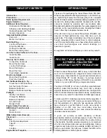
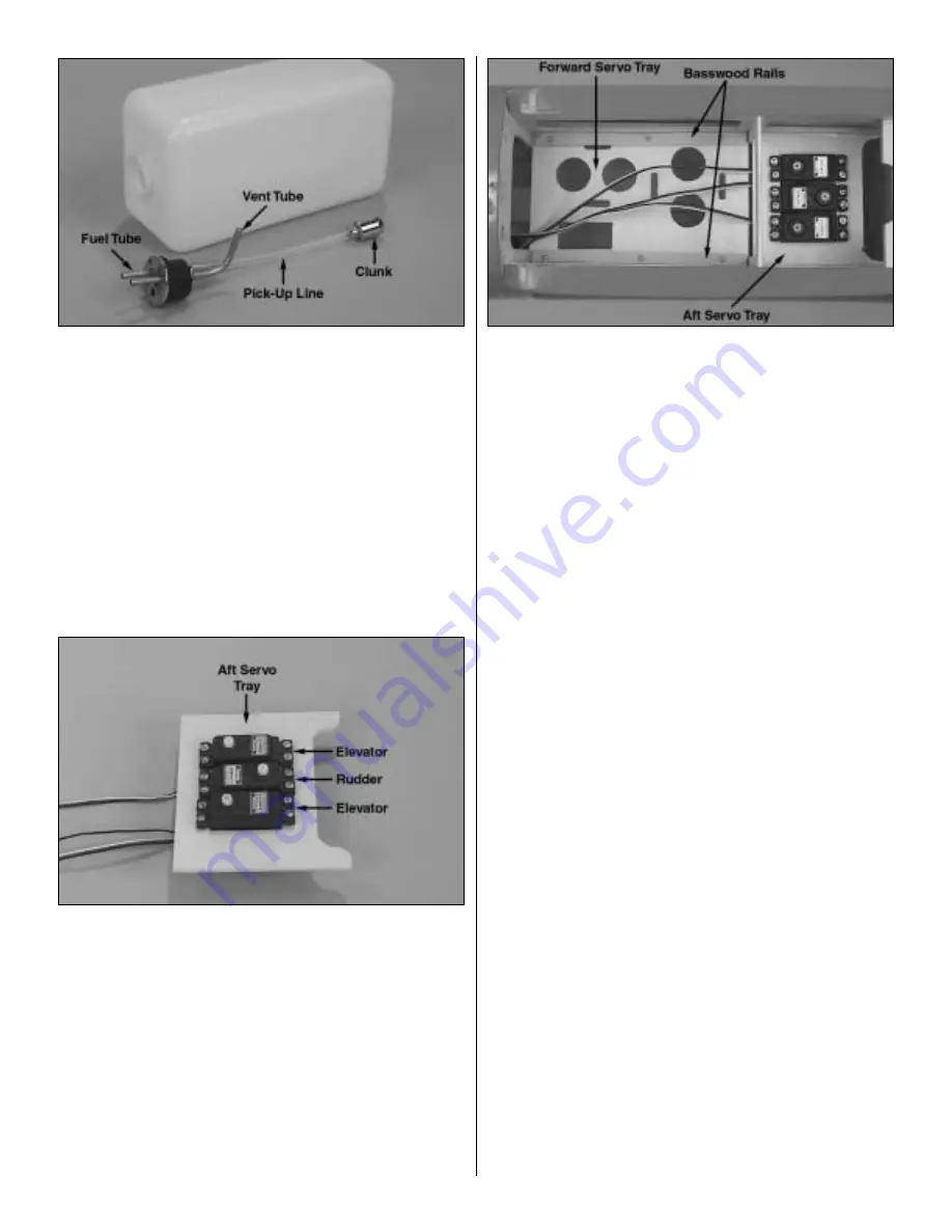
3. Assemble the fuel tank. Arrange the stopper and tubes
as shown in the photo, then fit them into in the tank. Tighten
the screw to expand the stopper, thus sealing the tank. Be
certain the fuel line weight (clunk) at the end of the fuel line
inside the tank does not contact the rear of the tank.
Otherwise, the line may become stuck during flight and
discontinue fuel flow. Remember (or use a felt-tip pen to
mark) which tube is the fuel pick-up tube and which tube is
the vent (that will be connected to the pressure fitting on the
engine muffler).
❏
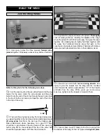
4. Install the fuel tank so the neck fits through the hole in
the firewall. Be certain that you have installed the tank so
the vent tube inside the tank is pointing upward. Use #64
rubber bands (not included) to hold the tank to the tank floor.
❏
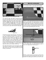
5. Test fit the rudder servo and both elevator servos in
the 1/8" plywood
aft servo tray
. Make adjustments if
necessary to the tray to accommodate your servos. Drill
1/16" holes in the tray for mounting the servos, then add a
few drops of thin CA to the holes and allow to harden. Mount
your servos.
❏
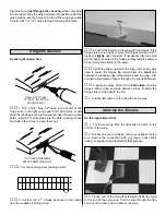
6. Before installing the 1/8" plywood
forward servo tray
,
use a pin to poke a hole through the fuselage sheeting at the
middle
of the
bottom edge
of the hardwood wing strut
mounting blocks on both sides of the fuse. The hole will be
a future reference for mounting the wing struts later on.
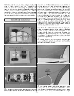
Refer to this photo for the following two steps.
❏
7. Securely glue the aft servo tray to the crutches using
epoxy (it may be easier to do this without the servos in the
tray). For additional strength, mix Great Planes Pro Milled
Fiberglass (GPMR6165) into the epoxy. Use clamps to hold
the aft servo tray in position until the epoxy hardens.
❏
8. Removal of the fuel tank will not be possible after the
forward servo tray is glued into position. If you would like to
be able to remove the fuel tank after the forward servo tray
is installed (for future maintenance to the tank), make the
forward servo tray removable. This can be done by using
epoxy to glue 3/16" x 3/8" x 6-3/8" (or a similar size)
basswood rails (not supplied) to the fuse crutches. Drill
three 3/32" holes through both rails before gluing them into
position. Use #2 x 1/2" screws (not supplied) to secure the
tray to the rails. If you prefer not to make the forward servo
tray removable, use epoxy to glue it into position the same
way you did the aft servo tray.
❏
9. Connect the rudder servo to the rudder using the pull-
pull cable system.
❏
10. Cut the covering from the elevator guide tube exits in
both sides of the fuse. Make two
elevator pushrods
by
threading a 4-40 nut and a 4-40 clevis onto two 4-40 x 36"
threaded one-end pushrods. Insert the pushrods into the
guide tubes with the clevises on the aft end.
12


