❏
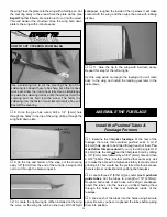
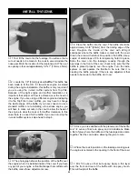
17. Position a large nylon control horn on the left side of
the rudder, over the plywood plate located under the
covering, aligning it with the pushrod. Use a T-pin to locate
exactly where the plywood plate is on the left side of the
rudder. Mark the location for the screw holes. Drill through
the marks you made with a 1/16" [1.6mm] drill bit, drilling
only through the plywood plate on the left side of the rudder.
Do not drill all the way through the rudder! Thread two
#2 x 3/8" [#2 x 9.5mm] sheet metal screws into the holes
you drilled. Remove the screws and apply a couple of drops
of thin CA into the holes to harden them. Mount the nylon
control horn to the rudder with two #2 x 3/8" [#2 x 9.5mm]
sheet metal screws.
❏
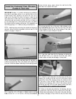
18. Cut another 36" [914mm] wire pushrod threaded on
one end to a length of 28" [711mm], making sure you cut the
wire off at the un-threaded end of the pushrod wire. Insert it
into the pushrod tube for the rudder. The threaded end of the
pushrod should be towards the rudder. Thread a nylon clevis
onto the threaded end of the wire 20 turns. Install a silicone
clevis retainer onto the clevis and then install the clevis on
the rudder control horn.
The following instructions are for installing an O.S.
®
.61
engine (OSMG05610) with the Top Flite in cowl muffler
(TOPQ7917) and Top Flite muffler header (TOPQ7920).
This combination of engine and muffler allowed us to
completely enclose the engine in the cowl. Because of this
enclosed engine installation, some engine baffling is
necessary and is explained once you proceed to installing
the cowl. The engine mount and installation instructions for
the engine mount will work for most .61-.75 two-stroke and
.91 four-stroke engines. If you choose to install your engine
with a standard muffler system you will need to make
different cut outs in the cowl than we will be showing in this
manual. Now is the time to determine the exact engine and
muffler you will be using.
❏
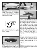
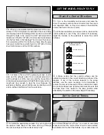
1. Locate the engine mount template located on page 39
of this manual. Cut the template from the manual.
❏
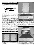
2. Molded into the firewall are lines that are for referencing
the location of the engine mount template. Using a felt-tip
pen, draw through the lines extending them further out to
each side of the firewall.
❏
3. Tape the engine mount pattern to the firewall, aligning
the pattern on the lines you have drawn on the firewall. Drill
a 3/32 [2.4mm] pilot hole through each of the marks in the
corners of the pattern. Then drill through the pilot holes with
a 7/32" [5.6mm] drill bit.
❏
4. Remove the template and install four 8-32 blind nuts on
the backside of the firewall. This is easily done if you insert
an 8-32 bolt into a #8 washer. Insert the bolt and washer
through the hole. Reach into the fuselage with the blind nut,
inserting it on the bolt. Tighten the bolt against the firewall,
pulling the blind nut into place. You should have little trouble
reaching into the fuselage to insert the blind nut. If you
should have difficulty you may find it easier if you remove the
forward former you installed earlier. Remember to re-install it
after the blind nuts are in place.
Install the Engine
INSTALL THE ENGINE & MUFFLER
17
Summary of Contents for Lancair ES
Page 40: ......

