


18
SPARE PARTS
●
Glow plug (OS #8 recommended - OSMG2691)
●
Propeller (GPMA4287)
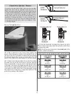
Selecting the correct
propeller for an airplane
is very important. Your
Avistar Elite RTF Select
comes equipped with a
specially designed nylon
12 x 5 propeller. These are
the features explained:
The propeller is made out of fl exible nylon so that it won't break
on light contact with the runway or weeds. If the propeller
ever gets in contact with anything while the engine is running,
inspect it before running it again. Check for cracks, scuffl ed
tips or unbalanced blades. If necessary, replace the propeller.
The Avistar Elite RTF was designed around an 12 x 5 propeller
for best performance. The 12 x 5 propeller helps keep the
airplane speed down at full throttle; it increases take off
performance on any surface, including tall grass; and it acts
as a brake when the nose is pointed down. Should you ever
need to replace the propeller, replace it with the same or
similar 12 x 5 propeller. There is no benefi t to using a larger
propeller or one with more pitch.
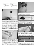
FUELING THE AVISTAR ELITE
The Avistar Elite comes with a three-line fuel line system. To
fuel the airplane, remove the fuel line plug from the fi lling
line (green) and connect the fuel pump to it. Disconnect the
clear line from the exhaust. Fill the tank until fuel comes out
the clear line. Re-connect the clear line to the exhaust nipple.
Replace the plug to the fi ll line. The airplane is now fueled.
To remove fuel from the fuel tank, remove the fuel line plug
from the fi lling line (green) and connect the pump to it. Pump
out any fuel that may be in the fuel tank. Replace the fuel line
plug to the green line.
NOTE:
You may have to lower the nose
of the airplane to completely de-fuel the tank.
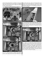
STARTING YOUR O.S. .46 AX II
Your OS .46 AX II has been optimized to be easy to handle
and start. The following comments are not intended to replace
the manufacturer's instructions but to complement them. After
many hours of testing, this is the best starting procedure we
have developed for this engine.
●
Make sure your fuel tank is fi lled with fuel. Any quality model
airplane fuel with 0% to 15% nitromethane content will
work well.
●
Make sure none of the fuel lines are kinked or pinched and
that fuel is free to fl ow into the carburetor.
●
The high-speed needle should be opened 2 turns out from
the closed position.
●
Set your throttle to wide open.
●
Cover the carburetor opening with your fi nger, grab the
propeller and turn it counterclockwise several times until
you can see fuel fl owing into the carburetor through the
carburetor line.
●
Install the glow starter to the glow plug (make sure it is
fully charged).
●
Set your throttle to idle (carburetor is about 3/64" [1.2 mm]
open).
●
To hand start the engine, use a chicken stick or thick gloves
to push the propeller blade rapidly through compression in
a counter-clockwise direction. Move your hands away from
the propeller immediately! It may take several tries to start
the engine, especially during the fi rst several runs while the
engine is breaking in.
●
After the engine has started, carefully remove the glow
driver from the glow plug.
●
Adjust the high-speed needle.
ADJUSTING THE NEEDLE VALVE
AND BREAK IN THE ENGINE
If you are starting your O.S. engine for the fi rst time, run
the engine for one minute with the throttle fully open and
the high-speed needle valve adjusted for rich, slow, “four-
cycle” operation. This fuel-rich setting provides an adequate
amount of lubrication to the engine during break-in. Four-cycle
operation has an erratic combustion sound accompanied by
rich smoke from the muffl er. Take care to make all needle valve
adjustments from behind the engine and keep your fi ngers
clear of the spinning propeller.
Now close the high-speed needle valve until the engine speeds
up to “two-cycle” operation. Engine pitch will increase and
become a clear, continuous combustion noise. Allow it to run
for about 10 seconds. Then, re-open the needle valve to bring
the engine back to “four-cycle” operation and run it for another
10 seconds. Repeat this procedure until the fuel tank is empty.
Re-start and adjust the needle valve until the engine just breaks
into “two-cycle” from “four-cycle” operation. The fi rst three or
four fl ights should be made with this needle setting. During
subsequent fl ights, the needle valve can be closed gradually
to give more power. To prevent “too lean” operation, do not
run the engine continuously at the highest rpm allowed by the
high-speed needle valve setting. The needle valve should be
richened from the highest rpm setting allowed by the high-


