GREAT PLAINS NP2540 Operator'S Manual Download Page 76

2019-04-12

Table of Contents

Index

417-459M

NP2540

Table of Contents

Index

Operating Instructions

72

Liquid Operations

Operations for anhydrous nitrogen fertilizer begin on

page 58.

Liquid: Filling On-Board Tanks

The tanks may be loaded from the quick-fill inlet, or from

the lids (page 73).
If the fertilizer solution has any tendency to settle,

sediment, gel, coagulate, precipitate or stratify, load

material immediately prior to application. The tank

system has no agitators for sustaining suspensions.
Apply fertilizer soon after material loading. Clean out

unused materials promptly. Fertilizer allowed to remain in

the tanks for an extended period can settle, resulting in

excessive or insufficient concentrations during

application. System plugging can also occur.
1. Hitch the applicator to a tractor. Filling an unhitched

applicator is not recommended, as it can increase

parking stand loads above the bearing capacity of

the soil.

2. Inspect the tanks from the lids.
3. Drain excess condensation from the tank, so that

this water does not dilute the material to be loaded.

See “

Material Clean-Out (Liquid)

” on page 127.

4. Flush the tank if there is other residue present.
NH

3

: Tank Quick-Fill

Refer to Figure 49

5. Position the applicator on level ground, or tanks may

fill unevenly.

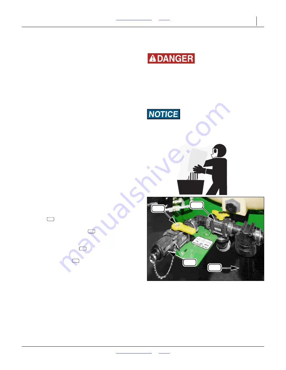
6. Connect the nurse-tank hose to the quick-fill

coupler

 located at the left end of the left tank.

Lock hose in place with cam-lock levers.

7. Open the discharge valve (

, not shown) of each

tank to be filled. If filling must be performed on

unlevel ground, fill one tank at a time.

8. Set the selector valve

 to “FILL” (handle arrow

pointing forward, toward elbow from inlet).

9. Open shut-off valve

 at quick-fill coupler.

10. Open any supply valve and fill tanks. Tanks are

marked with fill levels.

11. Close valve at supply, then quick-fill coupler, and

disconnect the nurse tank hose.

12. Set selector valve to OFF, or to PUMP if applying

immediately.

L17

L15

L16

L18

Figure 49

Inlet and Selector Valve

32082

Agricultural Chemical Hazards:

Observe safety precautions specified by material suppliers.
Some chemicals can cause serious burns, lung damage and

death. Avoid contact with skin or eyes. Avoid prolonged

breathing of chemical fumes. Wear respirator and other
protective equipment as required by chemical manufacturer.

Seek medical assistance immediately if accident occurs. Know
what to do in case of an accident.

System Plugging Risk:

Use only pre-mixed liquid fertilizer. Fill tanks at field,

immediately prior to application. Do not use dry mixes. Do not
leave material in tanks for extended periods.

L16

L13

L15

L17

Summary of Contents for NP2540

Page 1: ...ual NP2540 Nutri Pro 40 Foot Fertilizer Applicator Read the operator manual entirely When you see this symbol the subsequent instructions and warnings are serious follow without exception Your life and the lives of others depend on it Illustrations may show optional equipment not supplied with standard unit or may show models where the topic function is identical 34950 ...

Page 2: ...ered the weights and measurements are no longer accurate for your machine Update the record by adding the machine weight and measurements with the option s weight and measurements Dealer Contact Information Model Number Serial Number Machine Height Machine Length Machine Width Machine Weight Year of Construction Delivery Date First Operation Accessories Name Street City State Telephone Email Deale...

Page 3: ...Preparation and Setup 33 Initial Setup 33 Post Delivery Seasonal Setup 33 NP2540AA Get Expert Advice 34 Pre Application Setup 34 Hitching Tractor to Applicator 34 2 Point Hitching 35 NP2540AA Emergency Shut Off Rope 36 Electrical Hookup 38 Hydraulic Hose Hookup 39 Raise Parking Stands 40 Leveling Applicator 41 Meter Variable Rate Setup Option 42 Wash Water 44 Sealer Setup 44 Operating Instructions...

Page 4: ...acement 122 Replacement Log 123 Metering System Maintenance 126 Material Clean Out Liquid 127 Tank Clean Out 127 Liquid Fertilizer Strainer Maintenance 128 Pump Maintenance and Repair 129 Ace Hydraulic Pump 129 Coulter Disc Replacement 129 NH3 Coulter Spring Setting 130 Hydraulic Maintenance 131 Bleeding Lift Hydraulics 131 Bleeding Fold Hydraulics 132 Stop Fold Adjustments 133 Machines With Recta...

Page 5: ...u are new to NH3 operations study everything you can about this chemical and how to use it safely Suffocation Blinding Burning Freezing Disabling and Disfigurement Hazards Your life and health the lives and health of your workers and community the continued commercial availability of anhydrous ammonia and continuation of agricultural NH3 transport exceptions depend on you conducting meticulously c...

Page 6: ...hich if not avoided could result in death or serious injury and includes hazards that are exposed when guards are removed It may also be used to alert against unsafe practices CAUTION and the color Safety Yellow indicate a potential hazard which if not avoided may result in minor or moderate injury It may also be used to alert against unsafe practices Prepare for Emergencies Be prepared if a fire ...

Page 7: ...ors unless conventional liquid fertilize label specifies another type of respirator Waterproof unlined gloves Neoprene is recommended Cloth coveralls outer clothing changed daily waterproof items if there is a chance of becoming wet with spray Waterproof apron Waterproof boots or foot coverings Do not wear contaminated clothing Wash protective clothing and equipment with soap and water after each ...

Page 8: ...inches away from a human during use to comply with the RF human exposure limits as called out in FCC 47 CFR Sec 2 1091 DO NOT RE MOUNT OR USE THE RADAR IN A MANNER INCONSISTENT WITH ITS DEFINED USE Keep Riders Off Machinery Riders obstruct the operator s view Riders could be struck by foreign objects or thrown from the machine Never allow children to operate equipment Keep all bystanders away from...

Page 9: ...ines The folded fertilizer applicator could contact lines lower than 13 foot 4 m Overhead lines at farm structures are a particular hazard An incorrectly folded applicator is at risk from lines lower than 22 foot 7 m Watch for all electrical lines during folding and unfolding operations Use a spotter during folding and unfolding Know the location and height of all lines during transport and in fie...

Page 10: ...rement communities etc Avoid transporting an anhydrous ammonia tank through populated areas Do not tow a lift assisted 2 point applicator or nurse tank that when fully loaded weighs more than 1 5 times the weight of towing vehicle Do not transport a 2 point applicator that exceeds the capacity or ballasting of the tractor There may not be enough front wheel traction for safe steering Carry reflect...

Page 11: ... consult a doctor immediately with the chemical label or container in hand Any delay could cause serious illness or death Dispose of empty chemical containers properly By law rinsing of the used chemical container must be repeated three times Puncture the container to prevent future use An alternative is to jet rinse or pressure rinse the container Wash hands and face before eating after working w...

Page 12: ...r the fertilizer applicator weight Make sure all moving parts have stopped and all system pressure is relieved Allow applicator to cool completely Disconnect battery ground cable before servicing or adjusting electrical systems Welding Disconnect battery ground Avoid fumes from heated paint Inspect all parts Make sure parts are in good condition and installed properly Remove buildup of grease oil ...

Page 13: ...at Plains dealer Refer to this section for proper decal placement When ordering new parts or components also request corresponding safety decals Slow Moving Vehicle Reflector 818 055C Red Reflectors S N C1086J 838 266C To install new decals 1 Clean the area on which the decal is to be placed 2 Peel backing from decal Press firmly on surface being careful not to cause air bubbles under decal On a m...

Page 14: ...board side of light bracket and rear face outboard side of decal plate 4 total See Transport on page 56 68535 On the rear face outboard side of light bracket and rear face outboard side of decal plate 4 total See Transport on page 56 68532 On rear face of caster weldments below red reflectors and on rear face of inner wing weldments near pivot and outboard of red reflectors 4 total See Transport o...

Page 15: ...ight bracket and rear face inboard side of decal plate 4 total See Transport on page 56 On the rear face inboard side of light bracket and rear face inboard side of decal plate 4 total See Transport on page 56 68535 68532 On outside faces of caster weldments and on front faces of outside tank cradles on tankless models the forward reflectors are on the side faces of the front subframe 4 total See ...

Page 16: ... brackets and outside faces of side decal plates and front faces of outside tank cradles on tankless models the forward reflectors are on the front of the jack stands 6 total See Transport on page 56 68535 On outside faces of caster weldments and on front faces of light mount brackets 6 total See Transport on page 56 68532 On front or back side of Raven AccuFlow 2 or 4 total Order replacement from...

Page 17: ...der 1 total 31618 NH3 models On decal mount near Flo Max coupler 1 total See NH3 Operations on page 58 and separate manual Using Anhydrous Ammonia Safely 407 551M Conventional Models On left face of ground drive pump mount 1 total See Liquid Operations on page 72 Conventional Models On decal mount at optional rear hitch and or on front face of each center tank leg 1 total See Liquid Operations on ...

Page 18: ...ing near inner pivot 2 total See Remain Clear of Overhead Lines on page 5 To prevent serious injury or death Stay away from power lines when transporting extending or folding implement Electrocution can occur without contacting power lines 838 599C ELECTROCUTION HAZARD DANGER 32339 On decal mount near Flo Max coupler 1 total This decal summarizes the mechanical procedure for coupler re connection ...

Page 19: ...37C Rev B 32339 On front face front frame at right end and on left and right faces of parallel arm mounts 5 total See Hitching Tractor to Applicator on page 34 Wear proper hand and eye protection this type of injury If injured seek immediate medical help from a doctor familiar with hoses BEFORE applying pressure Visually check all hydraulic lines and Keep all components in good repair or cardboard...

Page 20: ...nformation 31604 This decal should not apply to 2013 NP2540A applicators but might be encountered on nurse tank valves or if repairs are made with old stock after market parts See Avoid Ball Traps on page 115 Older unvented ball valves can trap fluid inside the ball if closed with the line fully charged Great Plains ball valves shipped in 2011 and later have a bleed orifice on the downstream side ...

Page 21: ...face of gauge wheel arms 2 total See Tires Not a Step on page 4 38857 On front of front frame tube right and left of hitch 1 total See Important Safety Information on page 1 WARNING Cancer and Reproductive Harm www P65Warnings ca gov To prevent injury or death Read and understand Operator s Manual before using Lower implement stop tractor engine set park brake and remove ignition Do now allow ride...

Page 22: ...p all safety shields and devices in place Keep hands feet and clothing away from Never ride on machine Always lower or properly support machine Escaping hydraulic fluid can cause serious Review safety instructions with all operators moving chains and sprockets BEFORE servicing 818 587C Rev B injury annually CAUTION 32339 On rear face of caster weldments above red reflectors 2 total See Important S...

Page 23: ... 786C On front of front frame tube right of hitch 1 total See Liquid Operations on page 72 32339 On rim of each NP2540 lift assist wheel 2 total See Tire Safety on page 8 To Avoid Injury or Machine Damage from Improper Tire Inflation or Torquing of Wheel Bolts Maximum inflation pressure of tires is 80 psi Torque wheel bolts to 300 lb ft 848 801C CAUTION 32339 On outside face of gauge wheel arms 4 ...

Page 24: ...C General Safety First Aid Water Option 848 539C On front of front frame tube right of hitch 1 total See Lubrication and Scheduled Maintenance on page 140 36852 On left and right sides of the wash water tank 2 total See Ammonia Emergency Action in the Using Anhydrous Ammonia Safely manual 407 551M and Wash Water on page 44 31599 ...

Page 25: ...e is available for sectional and variable rate control Intended Usage Use the NP2540 Fertilizer Applicator only to apply compatible fertilizers Do not modify Great Plains provisioned components or install user provisioned components except as authorized or recommended by Great Plains Models Covered 2015 Document Family Figure 1 NP2540 Fertilizer Applicator 34950 Anhydrous Model configurable for tw...

Page 26: ...instructions to avoid damage to equipment and ensure desired field results This form sets off useful information about the current topic or forestalls possible misunderstanding Right hand and left hand as used in this manual are determined by facing the direction the machine will travel while in use unless otherwise stated An orientation rose in some line art illustrations shows the directions of ...

Page 27: ...___________ Further Assistance Great Plains Manufacturing Inc and your Great Plains dealer want you to be satisfied with your new NP2540 If for any reason you do not understand any part of this manual or are otherwise dissatisfied please take the following actions first 1 Discuss the matter with your dealership service manager Make sure they are aware of any problems so they can assist you 2 If yo...

Page 28: ...lout numbers A11 through A86 identify the same applicator and cart components throughout this manual A12 A13 A15 A57 A16 A17 A18 A14 A11 A47 A23 A48 A48 A47 A19 A21 A22 A34 A24 A42 A20 A27 A28 A33 A44 A41 A31 A30 A29 A26 A25 A32 A46 A43 A45 A49 A40 A36 A37 A35 A38 A39 A42 A49 A49 A49 A49 A58 Figure 3 Anhydrous Ammonia NH3 Plumbing Double Cooler w Section Control 36726 ...

Page 29: ...a complex operation requiring tools Consult the breakaway manual for details More significant matters are safing the applicator and nurse tank then correcting the cause of the breakaway See NH3 Breakaway Event on page 69 A15 Breakaway Hydrostatic Relief Valve In normal operation this valve never activates It is designed to open at 375 psi well above the 250 265 psi operating pressure of the nurse ...

Page 30: ...sed to chill the fluid passing from to A22 Cooler Intake Liquid NH3 enters the cooler here A23 Cooler Hydrostatic Relief Valve In normal operation this valve never activates NH3 can get trapped in the system between the emergency shut off valve and the On Off valve if both valves are closed while the system is charged As the liquid warms and pressure rises this valve protects the system with perio...

Page 31: ... minimum takes approximately 9 seconds A31 Master Shut Off Valve This is the normal control for starting and stopping application flow in the field for turns etc This component is an open closed solenoid valve controlled by the SCS 450 The MASTER switch on the SCS 450 controls this valve When power is off this valve remains at its most recent setting This valve has a visible indicator above the va...

Page 32: ...e power is off the valves remain at their most recent setting The valve balls are equipped with a downstream relief orifice A40 Row Flow Divider s This is a CDS John Blue Impellicone manifold It evenly splits the NH3 flow for distribution through the delivery tubes There are no operational items for this component A41 Flow Divider Manifold Inlet NH3 liquid flow enters the flow divider here A42 Flo...

Page 33: ...th ends free for transport and storage and both ends are 13 4 4 Acme be sure about which end is which Installing a hose backwards can result in needless excess NH3 release at unhitching or a line segment unprotected by bleed and or relief valves a Acme collars may be aluminum but all internal coupler components must be NH3 safe typically stainless steel A60 A12 Hose valves are typically hand wheel...

Page 34: ... opened first and closed first The withdrawal valve is the application outlet valve It is usually located on the tank top but may be located on the bottom It is color coded red or orange A61 Pressure Gauge Not Shown This gauge reports the pressure usually in psi of the NH3 gas at the top of the tank The reading varies with tank and ammonia temperature Suffocation Blinding and Burning Hazards Be up...

Page 35: ...se Tank on page 74 L2 Chain Anchor Two anchor points are provided for nurse tank safety chains L3 Rear Hitch Tongue Accepts a 1 inch 2 6 cm hitch pin L4 Cart Hitch A nurse tank cart must have a clevis hitch with a 1 inch locking pin The tongue must be able to elevate to a hitch height of 48 inches 122 cm above ground with the high clearance rear hitch and 381 2 inches 97 7 cm with the drop hitch L...

Page 36: ... 417 459M NP2540 Table of Contents Index Metering Overview 32 Hitch Option and Nurse Tank Components User Provisioned See page 31 for callout descriptions Figure 4 Trailing Nurse Tank Hitch 32349 L16 L17 L12 L11 L8 L7 L3 L2 L1 L6 L5 L4 ...

Page 37: ...remely hazardous and field PPEa is inadequate for such testing Malfunction of a custom system could result in a major release of NH3 gas or liquid Initial Setup Other first time infrequent setup tasks include Set lift assist valve page 174 Install meter console in tractor page 175 Install any Options not factory or dealer installed Post Delivery Seasonal Setup On initial delivery use with a new tr...

Page 38: ...e tires to pressure recommended and tighten wheel bolts as specified See Tire Inflation Chart on page 163 Hitching Tractor to Applicator This manual presumes the following recommended operations sequence 1 Hitch tractor to applicator for transport next page 2 Transport applicator separately from nurse tank page 56 3 Hitch nurse tank to applicator at field page 74 To prevent soil compaction on rows...

Page 39: ...lains may be needed to fit your quick hitch or tractor s 3 point arms Lower Links 11 8 in 28 6 mm I D x 17 16 in 36 5 mm O D 1 Adjust tractor lower links to maximize lifting height 2 Normally the lower arms engage pins in the lower holes of the applicator s three point lugs You may use the upper holes if necessary 3 Set tractor sway blocks to minimize side sway Set tractor hitch lift control to Fl...

Page 40: ...ed in the closed line prior to operating other valves or uncapping at a nearby Acme fitting If the line is discharged opening the valve may have no result or may release a small amount of NH3 vapor at low pressure If there is a low pressure release leave the valve open at the current position Move away up wind Return when the release concludes If the line was not discharged opening a bleed valve m...

Page 41: ...e at the next step Refer to Figure 10 which depicts the shut off valve closed 6 If the emergency shut off valve was closed open it 7 Locate the emergency rope 8 Inspect the attachment of the rope to the valve handle and the rope itself Replace the rope if cut frayed or worn If the handle connection is not secure take corrective action 9 Uncoil the rope Remove any knots 10 Route the rope forward an...

Page 42: ... standard Console flow harness connector optional Hydraulic harness Console pressure connector variable rate only Console speed connector optional and only if sensor radar mounted on implement ___________________________ Make sure tractor is shut down with accessory power off before making connections These connections may be made in any order The key requirement is that all connections be made pr...

Page 43: ...ld cylinder rod end lift cylinder base end or the pressure side of a hydraulic motor Use a regular remote and not a dedicated tractor 3 point remoteb Secure hoses and cables so that they have sufficient slack for hitch movements but cannot get caught between moving parts of fertilizer applicator Failure to safely route and secure hoses and cables could result in damage requiring component repair r...

Page 44: ... the neutral position for the tractor hydraulics so that the hydraulic lever can only be moved to the float and down positions Refer to the tractor operator manual or tractor dealer on information for the neutral stop 4 See page 76 for setting flow rate Raise Parking Stands Refer to Figure 14 Heavy Object Hazard Use the lifting handle Push leg against frame while raising or lowering The leg weighs...

Page 45: ...entative conditions Front to Back Level Spacers The rear lift assist assembly must be set to match the gauge wheels and 2 point hitch in front Lift assist lowered height is controlled by provided spacers on the lift cylinder rods To set 1 Lower applicator until lift assist wheels are just off the ground 2 Raise applicator until wheels touch ground just firmly enough to resist spinning Refer to Fig...

Page 46: ...ystroke sequence for setting each of these values This data is retained as long as the SCS 450 remains connected to battery power If power is removed for electrical work long term tractor parking or welding the data is lost and must be re entered SCS 450 BOOM CAL Anhydrous models without section control have one boom section BOOM 1 whether single or dual cooler The BOOM CAL number is simply the ap...

Page 47: ...he pressure transducer in system diagrams in this manual Perform this operation only when lines are at zero pressure SCS 450 RATE 1 CAL This is your primary desired application rate typically in gallons per acre SCS 450 RATE 2 CAL This is your secondary desired application rate typically in gallons per acre If you have no alternate rate preferred set this to RATE 1 CAL so that the control valve wo...

Page 48: ...Sealer Adjustments on page 86 Model Description BOOM CAL SPEED CAL METER CAL VALVE CAL 1 LH 2 CTR 3 RH NP2540AA 16S30 NP2540AA 16C30 w o Section Control 40 Foot 16 Row 30 inch 480 0 in 1219 2 cm 598a a Suggested initial value Refine using calibration procedure in Raven SCS 450 manual Cable Tagb b This value is printed on a durable tag attached to the meter cable Body Labelc c This value for exampl...

Page 49: ... Information on page 1 Empty the applicator s 10 gallon wash water tank Refill it with fresh clean water Review the Material Safety Data Sheet MSDS for the anhydrous ammonia Check that all time dated applicator components are still within their specified service lives Check all plumbing components hose tubing and fittings are in satisfactory working condition Lubricate fertilizer applicator as ind...

Page 50: ...harness The harness must be connected at the hitch for the function to be effected Switch Positions PARK All solenoid valves are powered off and are spring loaded to flow open positions Use this position only for parking to save tractor battery power With the switch in PARK any hydraulic flow to the fold lift circuit may have undesired results FOLD UNFOLD Full fold and unfold sequence is controlle...

Page 51: ...mpacts during transport When not engaged the pins are stored in tubes at the base of the rest weldment See Folding on page 55 Outer Wing Fold Latches Refer to Figure 22 These latches are automatic and should never require operator action The latches couple the outer wing to the inner wing when folded preventing movement of the outer wing during transport the two outer wings might otherwise be able...

Page 52: ... 2 Verify that wing lock pins are installed on the folded wings page 47 3 Raise the tractor 3 point hitch just enough to lift the parking stand bases off the ground Set the hitch circuit to Neutral Shut off the tractor 4 Raise the parking stands page 40 The FOLD FIELD switch may be in any position for lift while folded Gradual Crushing Hazard Do not rely on hydraulic pressure alone to keep the app...

Page 53: ...This arrests fold at field lift 4 Retract the fold lift circuit until lift assist and wing fold operations each their stops Set fold lift circuit to Neutral Shut off the tractor engine leaving the FOLD FIELD switch powered upa 5 Raise the parking stands page 40 a If the FOLD FIELD switch is wired directly to the tractor battery the tractor may be shut off completely Otherwise leave the ACC active ...

Page 54: ...e wing fold cylinders and extend the lift assist Wing sections partially fold 4 Set hitch and fold lift circuits to Neutral for extended turns or field moves Figure 25 FOLD FIELD Switch for Field Lift 34918 Gradual Crushing Hazard Do not rely on hydraulic pressure alone to keep the applicator raised Use parking stands page 40 and locks page 47 when working around a raised applicator The tractor hi...

Page 55: ...rcuit to Neutral or Float 3 Remove the wing lock pins page 47 Refer to Figure 27 4 Set the FOLD FIELD switch to FOLD UNFOLD This arrests unfolding at wings level 5 Extend the fold lift wing to unfold the wings until wings level 6 To keep all coulters off the ground when unfolded and lowered crank the gauge wheels to full extension 7 If the tractor hitch is raised lower it until the applicator rest...

Page 56: ...avoids both of these risks The following instructions presume a lowering while stationary Refer to Figure 28 1 Verify that the FOLD FIELD switch is set to FIELD 2 Check that wings are partially folded in field lift or at least level If they are drooping retract the fold cylinders to correct 3 Lower the tractor 3 point hitch to the preset field height Set the hitch circuit to Position or Depth Cont...

Page 57: ...st off the lock channels 5 Set all circuits to Neutral Shut off the tractor 6 Remove the lift assist lock channels page 47 Install the spacers page 41 7 If wing gauge wheels were extended crank them to field height 8 Lower the hitch to field height Notes about normal unfold Inner wings unfold first The outer wings are constrained by the wing latches page 47 Outer wings unfold last The wing latches...

Page 58: ...l 9 Shut off the tractor 10 Unless using blocks or stands under wings fully extend wing gauge wheels 11 Deploy parking stands at desired or maximum height 12 Start the tractor Lower the 3 point hitch until the applicator rests on the parking stands at front 13 If wings stop above horizontal move switch to FIELD position and Extend fold lift to further unfold 14 Extend until the gauge wheels contac...

Page 59: ...ad lines with or without direct contact It is also too high for safe transport Refer to Figure 34 3 Raise the hitch 4 Retract the fold lift circuit to simultaneously raise and fold the applicator Observe the fold sequence Lift and fold do not start and end at the same time If an abnormal fold is detected set the fold lift circuit to Retract then Neutral at wings level Troubleshoot the problem 5 Se...

Page 60: ...f Control Hazard Never use the applicator to tow a nurse tank on public roads Tow the tank to the field with a separate vehicle The applicator cannot provide sufficient lateral control of a trailing cart at highway speeds The total weight of the train can also easily exceed the steering and or braking capability of the tractor A tank upset could occur during normal highway maneuvers The resulting ...

Page 61: ...cator page 49 4 Install lift cylinder locks page 47 5 Fold applicator if unfolded page 53 6 Plan the route Avoid steep hills 7 Always have lights on for highway operation 8 Do not exceed 20 mph 32 km h Comply with all national regional and local laws when traveling on public roads 9 Remember that the fertilizer applicator may be wider than the tractor Allow safe clearance 10 Transport slowly over ...

Page 62: ...r convention liquid fertilizer begin on page 72 NH3 Nurse Tanks Use nurse tanks with proper current safety certification and current safety equipment and features Consult with your anhydrous ammonia supplier for safety information and correct safe handling transport and use of anhydrous ammonia Consult with local and regional authorities on safe and legal use of anhydrous ammonia including emergen...

Page 63: ...that line section may have been closed with liquid NH3 present which later vented dislodging the cap It is also possible that the valve disc has deteriorated and is venting at normal operating pressures a Set console MASTER switch OFF b Set BOOM 1 BOOM 2a and BOOM 3a switches OFF c Turn POWER switch ON If the valves were open setting either MASTER or all BOOM switches off closes the On Off Valve d...

Page 64: ...monia odor hissing of escaping gas valve getting cold dripping or spraying fluid 9 If there are any signs of residual NH3 leave the bleed valve open until the ammonia has vented and the inlet fittings have re warmed to ambient temperature This could take tens of minutes if the applicator was recently and improperly shut down 10 Close the bleed valve at the pressure temperature gauge at the outlet ...

Page 65: ...pting the tank NH3 Mechanical Cart Hitching 1 Spot the applicator Three objectives are Refer to Figure 51 2 Bring the applicator rear hitch tongue and nurse tank cart tongue into close proximity a few inches 3 Push down on the red tongue release handle This frees the applicator rear hitch tongue to extend 7 inches 17 8 cm to the rear and 9 inches 23 cm to either side to assist with cart tongue ali...

Page 66: ...ee to swivel relative to pointing directly rearward horizontal by at least 80 to each side 45 up and 20 down 4 Remove the Acme cap on the inlet side of the break away coupler Refer to Figure 42 5 Inspect the inlet Acme threads Clean away any debris or other contamination Blinding Choking and Respiratory Hazard Never look directly into an ammonia hose or fitting Use a mirror Always assume that ammo...

Page 67: ...plug Inspect the outlet Acme threads Clean away any debris or other contamination Refer to Figure 43 11 Route the cart hose along the cart tongue securing it to any clamps or caddies provided Do not clamp or tie the hose within 3 feet 92 cm of the breakaway coupler inlet Allow at least 13 inches 33 cm slack in the hose within the first 3 ft Do not allow excess slack that could allow the hose to sn...

Page 68: ...e odor and fail to notice when concentrations get dangerously high NH3 Start of Pass Planning Ideally you want NH3 to begin flowing out of the tines right at the start of a pass with the tines already in the ground This minimizes atmospheric releases Depending on wind direction tractor capability available headlands and field conditions there are several ways to start each pass A Capable Tractor L...

Page 69: ...ith the MASTER and BOOM 1 2 and or 3 switch on the On Off valve s remain OPEN the Control Valve retains its setting and ammonia may continue to flow from the nurse tank to the tines See SCS 450 manual for monitor operation details NH3 Field Application NH3 Starting Tank Flow 13 Spot the applicator at the start of the first pass 14 If the tractor has adequate power lower the tines into the ground a...

Page 70: ...itch ON 26 Set the MASTER switch to ON 27 Set the BOOMS 1 or BOOMS 1 2 3 switches on to ON 28 Select the desired RATE preset 29 Lower applicator to operating depth if not already lowered and begin first pass NH3 Possible Chemical Hazard Anhydrous ammonia is now flowing into the ground Some routinely escapes to the atmosphere Check for leaks Take action if strong odor is detected or a leak seen Tur...

Page 71: ...d strike the applicator be upset and leak On 2 Point and Pull Type the nurse tank tongue could strike the caster tires On 3 Point the nurse tank tires could strike sealers or tine shanks c Turn up wind for the next pass d Line up per your start of pass plan e Lower the applicator into the ground f Set the MASTER switch ON g Pull forward and complete the pass Choking Hazard Never raise a recently o...

Page 72: ... m Turn so that the wind is directly from the right n Open all bleed valves Standing up wind of each and making sure orifices point away from you slowly open bleed valves at nurse tank hose inlet end nurse tank hose outlet end breakaway valve or whichever is safer cooler temperature gauge o Close all remaining operating valves nurse tank hose inlet end nurse tank hose outlet end emergency shut off...

Page 73: ...cross wind of the tank so that you are not exposed to residual applicator fumes while working around the tank Face the tractor into the wind 6 From up wind approach the nurse tank 7 Close the nurse tank withdrawal valve 8 From up wind approach the nurse tank hose outlet end 9 Locate a bleed valve on the nurse tank half of a coupler Be careful not to touch or loosen the Acme coupler Bleed only one ...

Page 74: ...13 Close all breakaway bleed valves x and and any nurse tank hose valves Disconnect the nurse tank half of the breakaway coupler at the Acme coupler 14 Correct the cause of breakaway only if trivial to do in the field 15 Consult the breakaway manual for re coupling instructions Before Re connection Elevated Exposure Hazard Exercise extreme care Even if the nurse tank is undamaged sound and upright...

Page 75: ...upler inlet bleed valve g Stand clear and wait for the hoses to discharge h From the up wind side unscrew the nurse tank hose outlet coupler Secure the hose using whatever means the cart provides i Close all opened bleed valves j Release the nurse tank safety chains k Remove the nurse tank hitch pin NH3 Final Nurse Tank Unhitch a Conclude NH3 application per NH3 Stopping Application on page 68 The...

Page 76: ...Refer to Figure 49 5 Position the applicator on level ground or tanks may fill unevenly 6 Connect the nurse tank hose to the quick fill coupler located at the left end of the left tank Lock hose in place with cam lock levers 7 Open the discharge valve not shown of each tank to be filled If filling must be performed on unlevel ground fill one tank at a time 8 Set the selector valve to FILL handle a...

Page 77: ...y unscrews for a 7 in 18 cm opening 16 Insert the supply hose 17 Open the supply line valve Monitor tank level Fill to desired level Close supply valve 18 Remove hose Close and secure the tank lid The lid has twin threads Make sure that both are evenly engaged when tightening the lid and that the lid is fully seated L12 Figure 50 Tank Lid Closed and Open 32083 Chemical Hazard Tank Lid For top load...

Page 78: ...in 5 Securely attach the cart s safety chain s to the hitch chain anchor s 6 Optionally re seat the applicator rear hitch tongue at this time by using the tractor to move the applicator backward several inches until the latch on the hitch re engages Liquid Making Nurse Tank Connections 1 Close shut off valves on all hoses of both tank and applicator 2 Route tank supply hose to applicator inlet All...

Page 79: ...f planting apply it to the last field planted 22 Clean out fertilizer system per page 127 Liquid Pauses and Turns Ground Drive Pauses and Turns When the applicator is stopped or lifted the pump stops The boom is still pressurized but this bleeds down to 8 psi very quickly seconds at which point the nozzle clamp check valves close off flow to the rows Hydraulic Drive Pauses and Turns If the applica...

Page 80: ...pump for pump priming Close and cap or plug any tank fill inlet valves such as in the Great Plains plumbing system 2 Check that tank valves such as discharge transfer selector are configured and ready for use In the Great Plains tank plumbing system this would be tank discharge valves open to selector valve selector valve open to tanks and pump 3 On suitable ground raise the applicator Possible Ag...

Page 81: ...TER switch is not usually necessary if the console has an active speed sensor data source If suspending application for more than a minute also set the pump motor hydraulic circuit to Float No console actions are required to suspend application with ground drive preset or variable rate Liquid Stopping Application 1 Ground Drive If possible plan final passes so that they occur prior to tank run out...

Page 82: ...n 87 Check tubing connections to tines NH3 Check tine outlet behind shoes NH3 Check shoe condition NH3 Check tine shoes all at same height NH3 Check tine shank alignment NH3 Check outlet behind arms Check coulter blade condition Check coulter depth 88 Check NH3 sealer adjustments 86 Check spider condition Mechanical Checklist post Hitching Page Remove wing lock pins 47 Fully raise applicator 49 Un...

Page 83: ...r 62 Check withdrawal valve and all nurse tank hose valves closed 63 Check for signs of liquid NH3 in hose 63 Separate hose and Acme plug 63 Route hose to breakaway 63 Connect hose to breakaway 63 Plumbing Checklist Page Tank s loaded Supply hose shut off valve closed 26 NH3 Discharge valve s open to pump NH3 Vent if any open Tank hose s routed to applicator connectors mated and locked 31 Hose sla...

Page 84: ... Enter tractor cab Check ropes present with nominal slack 77 14 Console Option POWER on MASTER on RATE as desired 77 15 Lower applicator a hitch lower then Depth Control b cab switch to FIELD c wings extend then low rate continuous extend 52 16 Begin first pass setting switch MASTER to ON 77 17 NH3 Hydraulic remote for hydraulic pump to preset 75 18 Monitor the console Option for expected reports ...

Page 85: ... nurse tank withdrawal valve 68 38 NH3 Re enter cab Turn MASTER switch ON 39 NH3 Resume field application Raise flow rate to maximum 68 40 NH3 Continue application until cooler and flow divider pressures are zero 41 NH3 Turn into wind 42 NH3 Raise applicator and stop 48 43 NH3 Set MASTER switch off 44 NH3 Wait one minute 45 NH3 Turn left wind from right Stop 46 NH3 Open all bleed valves 68 47 NH3 ...

Page 86: ...ment Damage Risk Ground Drive Liquid Pump Keep the piston pump wet Fertilizer suffices for short term parking Flush with water for longer term parking Add RV antifreeze for winter storage See page 127 Failure to properly care for your pump and other cart components can lead to serious equipment damage in a relatively short span of time 1 Conclude application per NH3 Stopping Application on page 68...

Page 87: ...ments 88 Anhydrous Fertilizer Rate 65 Application rate Conventional Liquid Fertilizer Rate 94 Application rate Select and Install Orifice Plates 97 Consistent application rate across rows Ground Drive Range 100 Minimum and maximum application rate Strainer Adjustment 99 Minimize cavitation and orifice clogging Ground Drive Setting Relief Valve 100 Prevent system damage and material loss Ground Dri...

Page 88: ...lter blades wear Loosen the nuts on the U bolts Lower the shank and re tighten S N C1083J and above Tines are to be installed as high as possible on the tine mount and within 1 8 inch of the back of the blade Design coulter operating depth is 3 to 7 in 7 6 to 18 cm Operation below 7 in 18 cm is not recommended as high rates of disc wear are likely Application depth is unaffected by the coulter spr...

Page 89: ... To unlock the coulter loosen the jams nut at Loosen the set screw bolts at then tighten the jam nuts Do not loosen the stop bolts Anhydrous Coulter Blade Wear Blade wear is normal and the rate of wear varies with field conditions and operating depth Consider replacing the blade when the initial diameter has been reduced by 1 to 2 inches Although a nominal 22 inches in diameter blades are lightly ...

Page 90: ...the system With the tines out of the ground there could otherwise be releases of ammonia at dangerous concentrations Sealer Down Pressure Adjustment The following trip down pressures are available These values are per sealer arm and are with the coulters in the ground and arms slightly raised per nominal factory assumptions as depicted in Figure 53 on page 84 With the applicator raised position ha...

Page 91: ...ce of 5 4 in 13 7 cm from frame bottom to top of Terra Tine mount Height may be adjusted at the mount set screw or at the frame clamp Changing arm angle also changes tine height 4 The factory setting for arm angle is minimum pivot mount hole closest to Terra Tine mount Terra Tine Down Force Refer to Figure 60 A series of three holes in the spring adjuster and pivot mount plate provide five combina...

Page 92: ...an increase the spring down force to compensate In light but rocky conditions the factory spring setting may be higher than needed You can extend blade life by reducing the force at which the blades ride up over obstructions Applicator weight in almost all applicator configurations is generally sufficient to load the coulters to the full 400 pound factory setting Setting all springs above 400 poun...

Page 93: ...ht Coulter Height Adjustment Coulter height is the main control for application height Coulters may need to be lowered for rows in tracks Coulters applicator wide need adjustment as blades wear Coulters may also be set for rigid row alignment or limited castering For fields where frequent sharp turns are unavoidable you can reduce coulter plowing by allowing the coulters to caster at the pivot cas...

Page 94: ...al weight kit with some lighter triple coulter configurations If all springs are continuously in compression the coulters can lift the wing frames off the ground at the gauge wheels resulting in uneven coulter depth and or uneven seed depth If already operating at maximum down pressure reduce coulter depth To adjust the coulter spring Refer to Figure 61 1 Raise the applicator and install transport...

Page 95: ...per or cardboard NOT BODY PARTS to check for suspected leaks Wear protective gloves and safety glasses or goggles when working with hydraulic systems If an accident occurs seek immediate medical attention from a physician familiar with this type of injury Crushing Hazard Keep body parts clear of wings row cleaners and coulters while adjusting Keep all bystanders well away You will be seriously inj...

Page 96: ... conditions unfold page 53 applicator 2 Set FOLD FIELD to FIELD 3 Lower applicator page 48 and set or check application depth page 41 4 Pull forward to put coulters in ground 5 Put tractor in Park and set parking brake 6 Set tractor to half throttle Extend the fold lift circuit unfold Lock lever for continuous operation 7 Adjust tractor flow control valve so the needle on the bypass gauge is in th...

Page 97: ... lift circuit to Neutral and shut off the tractor 5 Remove the hairpin cotter at a caster pin Have one person control caster position Remove the pin 6 Reposition caster as desired Insert pin Secure with cotter Repeat for other caster Loss of Control and Machine Damage Risks Never operate with one or both pins removed or with pins installed but not in a caster weldment tube Always install the caste...

Page 98: ...lates page 97 3 Check strainer screen size page 99 4 Ground Drive Set the ground drive Range page 100 and ground drive dial page 101 Hydraulic Drive Set the pump pressure page 104 set the desired rate on the console see 016 0159 831 Raven SCS 450 Installation Operation and Service manual 5 Check the manifold pressure and relief valve during operation page 100 Determining Application Rate Great Pla...

Page 99: ...4 8 224 25 15 8 5 0 234 26 16 5 5 3 243 27 17 1 5 5 253 28 17 7 5 7 262 29 18 4 5 9 271 30 19 0 6 1 281 31 19 6 6 3 290 32 20 3 6 5 299 33 20 9 6 7 309 34 21 5 6 9 318 35 22 2 7 1 327 36 22 8 7 3 337 37 23 4 7 5 346 38 24 0 7 7 355 39 24 7 7 9 365 40 25 3 8 1 374 41 25 9 8 3 384 42 26 6 8 5 393 43 27 2 8 7 402 44 27 8 8 9 412 45 28 5 9 1 421 46 29 1 9 3 430 47 29 7 9 5 440 48 30 4 9 7 449 49 31 0 ...

Page 100: ...3 15 3 4 9 215 24 16 0 5 1 224 25 16 7 5 3 234 26 17 3 5 5 243 27 18 0 5 7 253 28 18 7 6 0 262 29 19 3 6 2 271 30 20 0 6 4 281 31 20 7 6 6 290 32 21 3 6 8 299 33 22 0 7 0 309 34 22 6 7 2 318 35 23 3 7 4 327 36 24 0 7 7 337 37 24 6 7 9 346 38 25 3 8 1 355 39 26 0 8 3 365 40 26 6 8 5 374 41 27 3 8 7 384 42 28 0 8 9 393 43 28 6 9 1 402 44 29 3 9 4 412 45 30 0 9 6 421 46 30 6 9 8 430 47 31 3 10 0 440 ...

Page 101: ...d pump wear use the largest orifice practical for your fertilizer application rate For rate ranges in liters per hectare see page 172 Material Loss or Misapplication Risks Orifice size must be appropriate for rate selected Drop line orifice plates do not affect rate on ground drive pumps and are not used to control rate on hydraulic drive pumps If the orifice size is too small over pressure in sys...

Page 102: ...ses take steps to avoid double application run those rows at half rate For doubled rows using standard nozzles use orifice plates having 1 2 or slightly more than 1 2 the Port Area of the other rows See the table at right right most column for the Port Area of each plate call size For doubled rows using VeriFlow nozzles install 829 144C half rate nozzles on those rows For either nozzle type an adj...

Page 103: ...ould be too low or too high Strainer Adjustment Refer to Figure 70 A Banjo brand strainer is supplied with the ground drive fertilizer pump It is plumbed before the CDS John Blue pump The standard 80 mesh screen should be suitable for most applications A 50 mesh screen is available from Great Plains Other screen sizes are available from Banjo Corporation If changing screen sizes keep in mind the f...

Page 104: ...ure gauge reads above 65 psi change to a larger orifice Go to step 2 Repeat steps Ground Drive Set Pump Drive Range Refer to Figure 72 Two Driving sprockets are provided for the pump Low Range 15T High Range 47T The choice of Driving sprocket depends on the application rate desired The pump adjuster dial see Figure 73 must be in the range 2 to 10 for consistent pump rate Use the rate chart to dete...

Page 105: ...und drive wheel and chain system operate whenever the applicator is lowered and in motion The pump must not be run dry VisaGage II Operation The VisaGage II flow monitor enables instant visual confirmation of liquids When the color coded indicator balls are floating in line the flow is proceeding at a uniform rate When an indicator ball floats lower the hose or opener supplied by that flow monitor...

Page 106: ...ne diesel etc Do not use in explosive atmospheres and do not use with anhydrous ammonia NH3 Failure to follow this notice may result in serious injury and or property damage and will void the product warranty If in doubt about your application contact your stocking dealer or the CDS John Blue Technical Staff at 1 800 253 2583 Use only glass or stainless steel ball with acid fertilizer The maximum ...

Page 107: ...ate table You may use the conversion table to adjust the flow values according to your fertilizer s lbs gallon measurement but it may be best to experiment with different balls to determine which one works best in your application Table Example For fertilizer weighting 11 lbs gal the conversion factor is 0 87 If you want to run 0 47 GPM through each monitor you need to divide 0 47 by 0 87 0 54 The...

Page 108: ...ncrease the hydraulic flow as needed to keep the psi in the 15 to 45 range 16 Reduce the RATE via the DEC switch to the desired field rate Verify that the pressure is still in the 15 to 45 range 17 Make a record of the flow rate setting for the hydraulic circuit 18 Set pump hydraulic circuit to FLOAT 19 Set console switches MASTER to OFF FLOW switch to RATE 1 Dead Head Adjustment This adjustment v...

Page 109: ...John Blue NGP Pump Parts and Instructional manual General Applicator Troubleshooting Problem Cause Solution Fold or unfold jerky or imbalanced Air in lines Bleed fold lift circuit page 132 Lift jerky or imbalanced Air in lines Bleed fold lift circuit page 131 Lift Assist casters oscillating Caster stabilizer too lightly set Increase spring tension on caster stabilizer piston page 143 Uneven applic...

Page 110: ...t stop at wings level Proximity switch damaged or disconnected Check 12 Vdc at solenoids Inner proximity switch Mis adjusted If 12 Vdc present check adjust switch see Stop Fold Adjustments on page 133 Field fold wings do not stop at gull wing Switch not in FIELD Check switch position and indicator lamps No power to switch or harness Check power to switch harness connections at hitch Defective swit...

Page 111: ...ency shut off valve to tines Wait for applicator to be safe to approach Check harness connections and fuses Use console SELF TEST mode to command Raven valves open Check valve ball indicators at valves Field speed too high higher than available pressure can supply NH3 Slow down or wait for warmer conditions Tank pressure low Ambient or tank temperature may be too low to provide sufficient delivery...

Page 112: ...heck for plugged row unit tube Stop application per page 68 Lift applicator and inspect tines Clear any plugging per Clearing Plugged Tines on page 118 Failed or malfunctioning aftermarket section control Consult system supplier documentation No Fertilizer Flow Strainer plugged Close all valves Inspect strainer page 126 Clean screen and magnets as needed Material run out Check tank level Temperatu...

Page 113: ...fine stopping and or lifting technique to avoid reverse coulter motion in ground Excessive NH3 loss to atmosphere all rows Application depth too shallow Check adjust tractor hitch page 41 lift assist spacers page 41 and gauge wheel height Coulters set too deep lifting tines Reduce coulter depth to tine depth page 84 Insufficient sealing Adjust sealers page 86 Test running dry Try multiple settings...

Page 114: ...nt to rear Check applicator front to back level page 41 Failed bearings Replace bearings Low Manifold Pressure Rate speed or material viscosity too low for orifice plate size Re check pump rate determination Range sprocket pump dial and console setup Option If correct replace orifice plates with a smaller size page 97 Strainer clogged Clean strainer and possibly use coarser screen size page 99 Gro...

Page 115: ...ve set too low Adjust relief valve page 103 Ground drive on Low Range when rate requires High Exchange Range sprockets page 103 Field Speed too low Increase speed or reduce orifice plate size Ground drive wheel or chains slipping Check condition of arm and chains Check operating height of applicator may be too high If soil is too wet try reconfiguring for a lower manifold pressure or wait for drie...

Page 116: ... flow meter Recheck console setup against values provided for components page 42 Control Valve failed or harness status Check harness connections and fuses Use console SELF TEST mode to command rate to zero Check indicator at control valve Command rate to maximum Check valve open Low Manifold Pressure Pump not primed Factory installed pump check bleed line for plugging Second pump open petcock val...

Page 117: ...almost invisible Use paper or cardboard not body parts and wear heavy gloves to check for suspected leaks Escaping fluid under pressure can have sufficient pressure to penetrate the skin If an accident occurs seek immediate medical assistance from a physician familiar with this type of injury 1 After using your applicator for several hours check all bolts to be sure they are tight 2 Ground Drive R...

Page 118: ...e that a closed valve represents a risk of trapped NH3 The illustration at right depicts a nurse tank hose in use and shut off while still full of liquid NH3 If this hose is removed to an enclosed space then opened it represents an extreme hazard Vapor concentrations could rise to well above IDLHa levels in moments This example system line segment is equipped with relief orifice equipped ball valv...

Page 119: ...ef valve those safety valves do not vent the ball cavity when a solid ball valve is closed One of them may vent just the downstream side of an orifice ball with the ball closed The emergency shut off valve supplied on Great Plains applicators in October 2010 and later has a relief orifice on the downstream strainer side of the valve See note on page 14 regarding valve Warning decal Nurse tank hose...

Page 120: ...in system discharge are NH3 liquid can remain in the system after the recommended stopping procedures NH3 liquid self cools as it evaporates slowing evaporation It can take a long time for all of it to turn to vapor particularly in cooler weather Once there is only vapor in the system there is usually little gas movement to drive the rest of it out The delivery tubing loops are usually the last to...

Page 121: ...w ambient temperature liquid evaporation is still in progress or has only recently completed Give the applicator more time to vent Steps continue on next page System Blow Out 4 To rapidly reduce the vapor in the system to trace amounts use compressed air at the Acme inlet a You will need to have the console connected to the meter harness and powered up Have the console up wind of the applicator b ...

Page 122: ...apor Your PPE is not designed to protect you against such a release Burning respiratory injury blinding or death could result a You will need a funnel with tip O D smaller than the delivery tube I D 3 8 inch 9 5 mm and a fresh water source b Face the applicator into the wind c Disconnect a delivery line at a flow divider outlet d Connect the funnel to the line e Add water until it appears at the t...

Page 123: ...flexible tool a coat hanger wire may suffice to clear the tine tube from above or below 5 Reconnect the application tubing Squeeze the spring clamp Slide it up the delivery tubing Push the delivery tubing onto the tine tube about 3 4 inch 19 mm Slide the spring clamp to centered in the overlap Clearing Closed Line Application Plugs 1 Review the WARNING at the top of this page 2 Stop operation page...

Page 124: ...n The vapor line may not cause a cloud The change in cooler pressure may be minor You are most likely to detect an open line plugging of a vapor line during routine row inspection at re hitch Clearing Closed Line Vapor Plugs 1 Review the WARNING at the top of this page 2 Stop operation page 68 3 Discharge the system page 116 The standard discharge is not likely to adequately discharge any plugged ...

Page 125: ...n for any lifted or missing hydrostatic relief valve caps If a cap is out of place that line section may have been closed with liquid NH3 present which later partially vented dislodging the cap Liquid NH3 may still be present Carefully bleed the line section before taking any other action It is also possible that the valve disc has deteriorated or has debris under the seat and is venting or leakin...

Page 126: ...arge the system page 116 before removing an old valve Wear protective equipment If the applicator was recently used or ammonia was trapped there could still be NH3 liquid or vapor behind the valve Do not attempt to repair or adjust a relief valve Hydrostatic relief valves are factory set and tested on specialized equipment to discharge at a specific pressure On the component being protected by the...

Page 127: ...ly anhydrous even if they appear to be in excellent condition Use this page or a copy to record the replacement schedule and history for your applicator Be sure to remove and save these pages or transfer the data if you update the manual itself Breakaway Coupler Hydrostatic Relief Valve Supply Hose Part ID Service Life Date Life Started Replace Before Date Great Plains 891 203C 5 years the replace...

Page 128: ...Valve Refrigerant Line This is the same tubing used for row delivery Part ID Service Life Date Life Started Replace Before Date Raven or Great Plains 334 0002 005 5 years the replace by date is stamped on the valve Part ID Service Life Date Placed in Service Replace Before Date Great Plains 990 259R Varies upon conditions A23 A3 A45 ...

Page 129: ...each tine from the flow divider Coil excess length Secure it to the rear tool bar at the row For wing rows coil inboard of the row so that the coil is below the tine when the applicator is folded Row Vapor Tubing This is a different larger ID tubing compared to the row delivery and refrigerant It might be necessary to replace it before the 10 year life if the tine end is damaged by harsh field con...

Page 130: ...ific recommendations for seasonal cooler storage cleaning and preserving the interior of the supercooler Cooler Hydrostatic Relief Valve This is a limited life part page 124 Check for expiration whenever servicing the cooler Flow Meter Maintenance If flow meter readings are irregular or consistently low relative to the amount of NH3 known to have flowed from the tanks remove the meter for cleaning...

Page 131: ...with 11 2 inch inside diameter Possible Chemical Hazard Operate the valves from above Wear chemical gloves Inspect the valves from below only when flow is shut off Wear eye protection when working under the tanks The valve operating handles have the word FLOW and a raised arrow that point in the open direction of flow This provides tactile indication of handle orientation 1 Connect any drain or co...

Page 132: ...emove the bottom canister of the filter 3 Wash the filter cartridge with water or replace with new cartridge if necessary 4 Reinstall the cartridge canister and turn on the ball valve End of Season Filter Cleaning 1 Load 10 to 15 gallons 40 to 60 liters of clean water in each supply tank 2 Pump most of it through the system If doing this by hand turning the ground drive wheel first install the lar...

Page 133: ...ructions Coulter Disc Replacement 22 Inch Coulters Replace 22 in 56 cm coulter blades when adjusting application depth and or applicator level becomes difficult Signs that blade replacement is indicated are Coulter blade diameter is close to or below 20 in 51 cm Height adjustment when level requires no lift assist spacers page 41 Tine height adjustment is at the upper limit page 84 See page 146 fo...

Page 134: ...ing loosen the outer jam nut Adjust the inner nut for a spring length of 103 8 inches 26 4 cm This corresponds to a vertical trip force of 1557 pounds 705 kg Machine Damage Risk Do not attempt to compensate for extreme field conditions by adjusting the springs to higher forces shorter springs Higher trip force is not likely to improve penetration and results in premature blade wear higher risk of ...

Page 135: ... O ring is likely to be torn if any pressure remains in the circuit Crushing Hazard When reconnecting fittings at fold cylinder rod end ports verify that an orifice plate is installed A missing plate could result in a dangerously fast unfold which might result in equipment damage injury or death See manual 417 459P for plate part numbers System Contamination Risk Always use liquid pipe sealant whe...

Page 136: ...Neutral 11 Orient cylinders with rod ends higher than base ends One cylinder at a time 12 Crack slightly loosen a JIC connection at a fold cylinder rod end 13 Extend the fold lift circuit slowly until fluid appears at the fitting 14 Set the fold lift circuit to Neutral Tighten the fitting 15 Repeat step 12 through step 14 for the remaining cylinders 16 Set fold lift circuit to Float 17 Re pin base...

Page 137: ...ximity sensor adjustment to compensate for hydraulic problems 2 Move the applicator to a solid level surface Raise and fold page 55 Install lift assist lock channels page 47 and parking stands page 40 3 Set the FOLD FIELD sensor to FOLD Extend the fold lift circuit to unfold until the inner wings stop Set the circuit to Neutral Shut off the tractor 4 Check the sensor to actuator gap at the affecte...

Page 138: ... lift assist lock channels page 47 and parking stands page 40 3 Set the FOLD FIELD sensor to FOLD Extend the fold lift circuit to unfold until the inner wings stop 4 Set the FOLD FIELD sensor to FIELD Retract the fold lift circuit until the wings stop at gull wing field lift page 50 Set the circuit to Neutral Shut off the tractor 5 Check the sensor to actuator gap at the affected wing pivot With t...

Page 139: ...the tractor key sensor to ON so there is electrical current to the fold proximity sensors There is a red and a green LED in each of the fold proximity sensors If no LED is illuminated at any of the fold proximity sensors check the power source for the tractor If neither LED is illuminated at a fold proximity sensor check the electrical circuit for that fold proximity sensor If the green LED is ill...

Page 140: ...tor key sensor to ON so there is electrical current to the fold proximity sensors There is a red and a green LED in each of the fold proximity sensors If no LED is illuminated at any of the fold proximity sensors check the power source for the tractor If neither LED is illuminated at a fold proximity sensor check the electrical circuit for that fold proximity sensor If the green LED is illuminated...

Page 141: ...ng level adjust gauge wheels Rear Eyebolt Adjustment Side to side level at rear is controlled by eyebolts at the lift cylinder bases Rear height is set by spacers page 41 Check that both eyebolts are set to the same reveal Refer to Figure 93 The factory setting is a distance of 4 5 in 11 4 cm from the end of the eyebolt to the top face of the lug tube To adjust the eyebolt loosen the hose guide nu...

Page 142: ...e Plate Adjustment Refer to Figure 94 and Figure 95 The factory setting for a new piston is 1 Loosen the jam nut 2 Turn the bolt counterclockwise until the bolt is turning freely 3 Drive screw in down until it contacts spring plate 4 Drive screw in until the bolt reveal from top of welded nut to bottom of bolt head is 2 0 inches 5 1 cm 5 Tighten the jam nut Use more or less tension as needed to el...

Page 143: ... longest span of each chain usually the span which does not run through the idlers 2 Determine the ideal slack Long chains over 36 in 91 cm 1 4 in per ft 21 mm m Vertical short chains 1 4 in per ft 21 mm m Horizontal short chains 1 2 in per ft 42 mm m 3 Measure the current slack Acting at a right angle to the chain span at the centre of the span deflect the chain in both directions The slack is th...

Page 144: ... 1 zerk each pin 2 pins per wing 4 zerks total Type of Lubrication Grease Quantity Until grease emerges Caster Pivots 1 zerk each caster 2 zerks total Type of Lubrication Grease Quantity Until grease emerges Torque on Hitches 2 hitches 2 nuts each U bolt 16 nuts total Amount of Torque 375 ft lbs 8 8 8 8 50 Multi purpose spray lubricant Multi pupose grease lubricant Multi purpose oil lubricant Insp...

Page 145: ...zer Pump Bearings Option 4 zerks per pump Type of Lubrication Grease Quantity Until grease emerges Refer to JohnBlue manual for pump maintenance Fertilizer Pump Crankshaft 2 inspection fill ports Type of Lubrication SAE 90 EP Gear Oil Quantity 8 fluid ounce capacity Refer to JohnBlue manual for pump maintenance Ground Drive Wheel Hub Option 1 zerk at each bearing casting 4 total Type of Lubricatio...

Page 146: ...re Pressures 2 lift assist tires 2 gauge wheel tires Check tire pressures more frequently on a new applicator and with new tires Check tire pressures before making any level adjustments and whenever there are application problems See page 163 for tire pressures Vantage I Coulter Hubs Option 1 zerk per coulter 12 to 48 total Type of Lubrication Grease Quantity Until grease emerges 20 20 Seasonal 31...

Page 147: ... Type of Lubrication Grease Quantity until resistance is felt Gauge Wheel Hubs 1 zerk each hub 2 hubs per applicator 2 zerks total Type of Lubrication Grease Quantity Until resistance is felt Caster Stabilizers One UHMW brake piston each caster 2 total See page 138 for inspection and adjustment Seasonal Seasonal Seasonal 34930 32318 1 2 31052 ...

Page 148: ...his kit adapts the applicator for use with tractors having Category II hitches Rear Hitches A rear hitch is required for a trailing nurse tank A nurse tank cart must have a clevis hitch with a 1 inch locking pin Two hitches are available a compact rear hitch and an extended shiftable hitch Both are drop hitches The nurse tank tongue must be able to elevate to a hitch height of 381 2 inches 97 7 cm...

Page 149: ...se the lighting harness for highway transport of nurse tanks or trailers behind an applicator At transport speeds on roads an urgent or emergency deceleration will result in a jackknife upset of a trailer Even normal braking above field speed risks loss of control The entire train can exceed the braking capability of the tractor particularly if a full tank is towed An accident is likely to result ...

Page 150: ...nk Configurations The shank rod of the 17th side dress coulter must be mounted on the rear face of the front tool bar to avoid interference with the fertilizer tanks in folding See Terra Tine Adjustments Option on page 87 Coulters Blades and Tines Anhydrous Coulters Figure at right shows a coulter with Turbo blade and notched spider sealers At time of publication a single anhydrous coulter configu...

Page 151: ...204 256A Single Fluted Coulters 12 204 257A Single Turbo Coulters 13 204 258A Double rear Fluted 14 204 268A Double rear Turbo 15 204 269A Vantage 1 20 Liquid Fertilizer Tines Part Bundle LH FERT TINE ASSY 204 262K RH FERT TINE ASSY 204 261K CLAMP WRM DRV 6 SS 800 390C 31655 31925 Nozzle Description Part Number Nozzle Description Part Number Solid Stream H1 4U SS0002 size 2 828 036C Solid Stream H...

Page 152: ...put already installed on the tractor Speed Sensor Cable If your existing or purchased speed sensor is compatible with the Raven 115 0159 539 cable intended for use with a Raven radar you may order it from Raven or from Great Plains Speed Sensor The Raven SCS 450 accepts speed inputs from traditional magnet sensors speed radars and GPS receivers that provide compatible speed outputs If the tractor ...

Page 153: ... in the manifolds assuring that each row obtains the same flow rate For a given rate there may be more than one orifice size that provides the recommended back pressure Plates are provided with the system in three sizes Additional sizes are available In general the orifice needs to be small enough to create a minimum pressure in the manifold but large enough to prevent the manifold pressure from e...

Page 154: ...ke steps to avoid double application run those rows at half rate For doubled rows using standard nozzles use orifice plates having 1 2 or slightly more than 1 2 the Port Area of the other rows See the table at right right most column for the Port Area of each plate call size Orifice Plate Size 20 28 34 48 59 80 98 Recommended Rate Range in Gallons per Acre Range is 15 40 PSI Nozzle Spacing Values ...

Page 155: ...oes not change the application rate If pump and or orifice size changes are not also made pressures could be too low or too high Variable Rate Nozzles These SprayTarget VeriFlow regulators replace the standard nozzles and orifice plates They provide consistent back pressure over a wide range of rates This eliminates changing orifice plates and enables prescriptions varying rates during application...

Page 156: ...without on board tanks The Ace pump includes all fittings needed for use with open center and load sensing LS or pressure compensating PC closed center hydraulic systems Fitting removal and or needle valve adjustment is required prior to first use see page 174 Hydraulic drive pump bundles 23 407 633A and 24 407 644A and require a new or existing Raven SCS 440 or SCS 450 controller and a new or exi...

Page 157: ...et and one set of orifice plates sizes 28 34 and 48 If a different size is required order one or more plates See page 149 407 907A Note Order the without coulter part number for use on triple coulter applicators that have both rear coulters and tine attachments on the rear coulters All of the rear coulters are removed during conversion to side dress one coulter its nozzle and drop line and its gre...

Page 158: ...ging no till conditions weight sets are available They add additional weight at the rear subframe The weight stacks are available as an Option with the original fertilizer applicator order or as a separate kit Used with NP2540AA 16C30 only Weight kit is not compatible with NP2540BL models See also Weight Kit Installation on page 184 Description Opt Part Number 2900 Weight Kit 70 407 740A 2500 Weig...

Page 159: ...6 ft 10 in Length 13 ft 8 in 15 ft 1 in Transport Width 16 ft 5 in Transport Height 13 ft 4 in Transport Clearance 16 in Min Tractor HP Req 180 255 hp 190 270 hp 180 255 ho 190 270 hp Hydraulic Circuits Req 2250 PSI 4 gal min Weight Min Empty 11 100 lb 5035 kg 11 350 lb 5148 kg 13 000 lb 5897 kg 13 250 lb 6010 kg Weight Max Empty 17 600 lb 7983 kg 17 850 lb 8097 kg 19 500 lb 8845 kg 19 750 lb 8959...

Page 160: ... CDS JohnBlue Impellicone Optional Controller Console Raven SCS 450 Optional Wing Flex 10 Working Height 6 ft 10 in Length 13 ft 9 in w o tanks 15 ft 1 in w tanks Transport Width 16 ft 5 in Transport Height 13 ft 4 in Transport Clearance 16 in Min Tractor HP Req 1 180 255 hp 190 270 hp Hydraulic Circuits Req 2250 PSI 4 gal min Weight Min Empty 2 12 500 lb 5670 kg 12 750 lb 5783 kg 12 850 lb 5829 k...

Page 161: ... JohnBlue pump or Ace hydraulic pump with Raven flow control Controller Console Raven SCS 450 Optional Wing Flex 10 Working Height 6 ft 10 in Length 13 ft 8 in 15 ft 1 in 13 ft 8 in 15 ft 1 in Transport Width 16 ft 5 in Transport Height 13 ft 4 in Transport Clearance 16 in Min Tractor HP Req 1 210 300 hp Hydraulic Circuits Req 2250 psi 4 gal min Weight Min Empty 2 11 500 lb 5216 kg 13 400 lb 6078 ...

Page 162: ...er Console Raven SCS 450 Option Wing Flex 10 Working Height 6 ft 10 in Length 13 ft 8 in Transport Width 16 ft 5 in Transport Height 13 ft 4 in Transport Clearance 16 in Min Tractor HP Req 180 255 hp 190 270 hp 180 255 hp 190 270 hp Hydraulic Circuits Req 2250 PSI 4 gal min Weight Min Empty 11 400 lb 5171 kg 13 300 lb 6033 kg 11 550 lb 5239 kg 13 450 lb 6101 kg Weight Max Empty 12 600 lb 5715 kg 1...

Page 163: ...Impellicone Option Controller Console Raven SCS 450 Option Wing Flex 10 Working Height 6 ft 10 in Length 13 ft 8 in 15 ft 1 in w tanks Transport Width 16 ft 5 in Transport Height 13 ft 4 in Transport Clearance 16 in Min Tractor HP Req 1 180 255 hp 190 270 hp 180 255 hp 190 270 hp Hydraulic Circuits Req 2250 psi 4 gal min Weight Min Empty 2 14 300 lb 6486 kg 16 350 lb 7416 kg 14 600 lb 6623 kg 16 6...

Page 164: ...6 ft 10 in Length 13 ft 8 in 15 ft 1 in Transport Width 16 ft 5 in Transport Height 13 ft 4 in Transport Clearance 16 in Min Tractor HP Req 210 300 hp Hydraulic Circuits Req 2250 PSI 4 gal min Weight Min Empty 11 700 lb 5307 kg 13 600 lb 6169 kg Weight Max Empty 14 200 lb 6441 kg 16 100 lb 7303 kg Weight Max Full 22 700 lb 10297 kg Transport Tire Size 265 70B 16 5 10 16 5 NHS 8 ply Skid Loader 4 1...

Page 165: ...ons These illustrations and measurements are the NP2540AA maximum case Dimension vary for liquid fertilizer and other NP2540AA configurations 34940 Overall 165 in 419 cm w o Liquid Tanks 181 in 460 cm w Liquid Tanks 160 in 406 cm Clearance 16 in 40 6 cm 197 in 501 cm From Hitch c l 150 in 381 cm w o Liquid Tanks 179 in 455 cm w Liquid Tanks ...

Page 166: ...mum case Dimensions vary for liquid fertilizer and other NP2540AA configurations 34941 496 in 12 6 m w Side Dress 467 in 11 9 m w o Side Dress Length from hitch c l w o Liquid Tanks 153 in 389 cm w Liquid Tanks 182 in 462 cm Overall Length w o Liquid Tanks 168 in 427 cm w Liquid Tanks 183 in 465 cm Field Height 5 in 13 cm depth Anhydrous 83 in 210 cm Liquid Only 79 in 201 cm 1 2 3 1 2 3 ...

Page 167: ...N m newton meters 11 2 6 1180 2640 4290 11 2 12 1330 2970 4820 c mm x pitch nominal thread diameter in mm x thread pitch Torque tolerance 0 15 of torquingvalues Unless otherwise specified use torquevalues listed above 5 8 8 8 10 9 25199 ft lbd ft lb ft lb ft lb ft lb ft lb 5 6 8 12 6 10 14 5 8 11 11 17 25 12 19 27 13 19 27 13 21 29 20 31 44 24 39 53 22 35 49 29 45 62 32 49 70 42 67 93 36 55 78 44 ...

Page 168: ...rant Line A14 Breakaway Coupler A34 Cooler Refrigerant Inlet A15 Breakaway Hydrostatic Relief Valve A35 Section Control Check Valve A16 Coupler Outlet Bleed Valve A36 Section Control Bleed Valve A17 Supply Hose A37 Section Control Relief Valve A18 Emergency Shut off Valve A38 Section Flow Divider A19 Strainer A39 Section Shut Off Valves A20 Strainer Magnets A40 Row Flow Divider s A21 AccuFlow Supe...

Page 169: ... 2019 04 12 Table of Contents Index 417 459M Chain Routing Option See also Chain Maintenance Option on page 139 Ground Drive Chain Legend Sprocket or idler Tooth count Chain Pitch count Direction of chain in motion 34T 56P 15T 25T 122 U D F B L R 31079 99P 47T 15T 15T ...

Page 170: ... of Contents Index Appendix A Reference Information 166 Controller System Diagrams Anhydrous Single Section Controller GP 823 211C GP 823 212C GP 823 215C GP 115 0159 539 GP 823 354C GP 063 0171 666 063 0172 977 063 0172 978 31580 Accessories sold separately ...

Page 171: ...Reference Information 167 2019 04 12 Table of Contents Index 417 459M Anhydrous Section Control Controller GP 823 211C GP 823 212C GP 823 215C GP 115 0159 539 GP 823 422C GP 063 0171 666 063 0172 977 063 0172 978 115 0171 836 063 0172 978 34966 ...

Page 172: ...n 168 Hydraulic Pump Controller GP 823 211C GP 823 212C GP 823 215C GP 823 237C GP 823 207C GP 823 208C GP 823 217C GP 823 236C GP 823 216C GP 823 222C GP 823 218C GP 115 0159 539 063 0171 793 063 0171 928 115 0159 415 POLARITY CABLE 063 0171 894 36047 Accessories sold separately Accessories sold separately ...

Page 173: ...NP2540 Table of Contents Index Appendix A Reference Information 169 2019 04 12 Table of Contents Index 417 459M Hydraulic Diagrams Hydraulic Schematic 34967 ...

Page 174: ...2019 04 12 Table of Contents Index 417 459M NP2540 Table of Contents Index Appendix A Reference Information 170 Proximity and Solenoid Locations 34998 ...

Page 175: ...NP2540 Table of Contents Index Appendix A Reference Information 171 2019 04 12 Table of Contents Index 417 459M Lift Assist Weight Transfer and Fold Hydraulics 68023 U D F B L R ...

Page 176: ...2019 04 12 Table of Contents Index 417 459M NP2540 Table of Contents Index Appendix A Reference Information 172 Pump Hydraulics Option 34948 ...

Page 177: ...ion to save battery power when the applicator is connected but not in use Route the captive harness to the hitch Secure it with the provided cable ties to prevent entanglement and damage NH3 Component Replacement Dates Record replace by dates on the Replacement Log pages 123 to 125 If the implement has Great Plains installed metering several components of that system have limited service lives and...

Page 178: ...e 1 Have the Ace Pump Instruction manual HYD MAN at hand for fitting use and adjustment details Refer to Figure 103 and table at right 2 Determine the tractor hydraulic system type Consult the tractor operator manual 3 Remove one or both fittings or and as necessary adjust the needle valve based on the system type Follow the instructions in the Ace manual For needle valve adjustment obtain dead he...

Page 179: ...rs Before first field use of the SCS 450 it must be programmed with data specifying the system configuration consisting of various CAL numbers and user elected RATE numbers See the Raven SCS 450 manual for display interpretation and see the manual of or the Calibration Card for the keystroke sequence for setting each of these values See Meter Variable Rate Setup Option on page 42 This data is reta...

Page 180: ... unfold and lift lower operations Hoist with 100 pound 45 kg capacity one fertilizer orifice plate sized to 1 2 of the rate intended or a 829 144C VeriFlow nozzle if 829 143C nozzles are used on the main rows Boom tap caps 830 061C for each active rear fertilizer drop line three dozen cable ties all purpose grease and grease gun basic hand tools Prepare Applicator 1 Discharge NH3 system page 116 i...

Page 181: ...e of the left wing outside row unit Use a grease pencil or similar means to mark the position for the side dress row unit on the extension weldment Install Coulter Mount This applies only to kit 407 907A and three coulter configurations For single coulter configurations kits 407 940A and 407 941A skip to Install Liquid Coulter on page 179 If the quick attach mount is already installed skip to Dism...

Page 182: ...ch rear coulter pivot disconnect the tubing from the grease bank Use a cable tie to secure all but the left most row s grease bank tubing to a U bolt at the front coulter clamp 17 If installed disconnect any fertilizer drop lines at rear coulters Disconnect at the push pull fitting Refer to Figure 109 18 Replace nozzles or with caps at each disconnected nozzle except the left most nozzle 19 At the...

Page 183: ...it 407 940A or 407 941A and single or 2 coulter configurations For 3 coulter configurations see Transfer Liquid Coulter on page 179 Refer to Figure 111 25 Select one each new 149 584D COULTER CLAMP 6H X 4W 204 691K NP COULTER ASSY RH two new 806 016C U BOLT 5 8 11 X 6 1 32 X 5 3 4 and four sets new 804 022C WASHER LOCK SPRING 5 8 PLT 803 021C NUT HEX 5 8 11 PLT 26 Align the coulter shank and clamp...

Page 184: ...o Figure 112 11 Measure a distance of one anhydrous row space from the center line of the left wing outside row unit Use a grease pencil or similar means to mark the position for the side dress row unit on the extension weldment Refer to Figure 113 12 Select one each new 417 121D FORMED SHANK CLAMP 2 OD 417 121L NH3 COULTER ROW UNIT ASSY two new 806 123C U BOLT 3 4 10 X 6 1 32 X 6 3 4 and four set...

Page 185: ...w 1 tubing all the way back to the section divider Do not disconnect it from the divider Measure the length of this tubing from divider port to row end cut Re route and reconnect it to row 1 Do not re tie until step 25 22 Select one new 990 259R EVA TUBING 3 8 ID Cut this tubing to the length measured at step 21 23 Select two new 800 400C HOSE CLAMP NO 10 593 ID SS Slide one over each end of the n...

Page 186: ...om the factory at the pre emergent setting of 16 09 inches from machine center 1 For side dress installation loosen or remove the nuts at all six bolts per hitch 2 Move each hitch to align on the frame as shown in Figure 112 3 Tighten nuts to torque specification shown on decal Figure 116 Pre Emergent Setting 36809 Figure 117 Hitch Shift 31844 17 39 39 31 9 Figure 118 Hitch Shift 36810 ...

Page 187: ...ate nozzle 4 Dismount side dress coulter Frame extension may be left in place 5 If a three coulter applicator move coulter to rear frame position from which it was removed Re install all other removed rear coulters 6 Restore hitch to center line 7 Note change in swath for rate calculations Revert Anhydrous Suffocation Blinding Burning Freezing Disabling and Disfigurement Hazards Do not perform thi...

Page 188: ...oist lines to the weight mounts 5 With the longer notch toward the wings and the shorter notch to machine center place the weight in the openings of the rear subframe Push it fully forward before releasing the lines 6 Repeat step 2 through step 5 for all weights 7 Select four sets 802 091C HHCS 1 2 13X1 1 2 GR5 803 019C HHCS 5 8 11X2 GR5 and eight 804 016C WASHER FLAT 1 2 SAE PLT Place a washer on...

Page 189: ... normal wear such as wear items and ground engaging components repeat repair due to improper diagnosis or repair by the dealer temporary repairs service calls and or mileage to and from customer location overtime premium or unit hauling expenses The warranty may be voided if the unit is towed at speeds in excess of 20 miles per hour 32 kilometers per hour or is used in soils with rocks stumps or o...

Page 190: ...e tank 58 caster angle 93 caster brake 138 caster stabilizer 143 castering 89 Category II 35 144 Category III 35 CAUTION defined 2 CDS John Blue 13 21 28 95 96 99 152 ceramic magnet 126 ceramic magnets 26 chain 139 chain anchor 74 chain clip 139 chains 3 check valve 27 75 checklists electrical 38 78 ending application 81 field 78 first pass 80 hydraulic system 78 mechanical 78 cart hitch 78 implem...

Page 191: ...ld bleed 132 FOLD FIELD 46 106 173 fold abnormal 55 fold normal 55 freezing 82 front to back level 41 fumes 8 FVC062 manual 1 G gasket 29 62 98 150 gauge pressure tank 30 gauge wheel 4 gauges pressure 27 28 37 temperature 26 gauge manifold 100 goggles 3 GPS 148 granules 3 grease in valve 122 green 151 green zone 92 ground drive 76 gull wing 46 H half rate 98 150 hand wheel 29 handle hose 39 harnes...

Page 192: ...illation 138 outlet cooler 26 overhead lines 5 55 O D Outside Diameter 35 P paint 82 PARK 46 82 173 parking 82 parking plug 71 parking stand 40 51 partial fold 49 50 parts 23 Parts manual 21 pass planning 64 PC closed 174 PEL 34 pesticide 3 pH 34 pin wing lock 47 piston 138 piston stabilizer 143 plastic sealant tape 131 plate orifice 131 149 plug flow divider 28 plumbing diagrams 164 Port Area 98 ...

Page 193: ...support 23 suspending application 67 swath 21 sway block 35 switch 173 symbol safety 2 T tables adjustments 83 document family 21 hose color 39 option manuals 21 orifice plates 98 150 orifice selection 97 149 pump NP30L 12R30 95 96 rates NP30L 12R30 95 96 tire inflation 163 tires 163 torque JIC 131 torque values 163 troubleshooting general 105 106 107 109 111 112 tank 144 tank connections 74 tank ...

Page 194: ...2 kph 6 334 0002 005 valve 124 339 9000 032 screen 126 40 option 144 400 DC cap 121 407 551M manual 1 7 27 58 61 407 707A Terra Tines 146 407 708A tankless 144 407 709A tank 144 407 725A pump option 152 407 740A 154 407 740A weight kit 184 407 776M manual 21 42 407 776P manual 21 407 906H extension 177 407 907A kit 177 178 179 407 907A side dress 153 407 940A kit 177 179 407 940A side dress 153 40...

Page 195: ...plate 98 832 053C plate 98 832 054C plate 98 832 055C plate 98 832 056C plate 98 832 057C plate 98 832 059C plate 98 833 637C switch 170 838 265C reflector 11 12 838 266C reflector 9 10 838 267C reflector 10 11 838 380C decal 18 838 599C decal 14 848 534C decal 14 848 539C decal 20 848 551C decal 16 848 736C decal 19 848 801C decal 18 19 85 psi 100 850 hitch 144 858 457C decal 20 891 196C hose 123...

Page 196: ...Great Plains Mfg 1525 E North St P O Box 5060 Salina KS 67402 ...

Reviews: