196-366m
Table of Contents
Index
Veris Drive Operating Instructions
Great Plains
| | 4/22/19
99
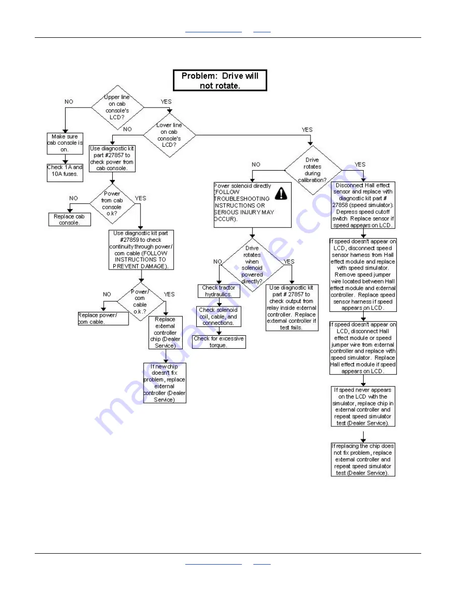
Troubleshooting Flow Chart
Page 1: ...9 Printed 4 22 19 Operator s Manual 3N 3010 and 3N 3020 No Till 21529 Illustrations may show optional equipment not supplied with standard unit Read the operator manual entirely When you see this symb...
Page 2: ...red the weights and measurements are no longer accurate for your machine Update the record by adding the machine weight and measurements with the option s weight and measurements Dealer Contact Inform...
Page 3: ...ll 20 Hitch Height Adjustment 21 Bleeding Hydraulics 22 Leveling Frame Side to Side 24 Box Alignment 25 Operating Instructions 26 Prestart Checklist 26 Folding the Drill 27 Rephasing Lift System 27 Un...
Page 4: ...68 Drive Operational Requirements 69 Tractor Hookup 70 Drive Calibration Number 73 Speed Calibration 79 Prior to Field Operational Use 82 Field Operational Use 82 Calibration Table 84 Varying Rates wi...
Page 5: ...ansport maintenance and storage of equipment Be Aware of Signal Words Signal words designate a degree or level of hazard seriousness DANGER indicates an imminently hazardous situation which if not avo...
Page 6: ...low children to operate equipment Keep all bystanders away from machine during operation Shutdown and Storage Lower drill put tractor in park turn off engine and remove the key Secure drill using bloc...
Page 7: ...es the weight of towing vehicle Carry reflectors or flags to mark drill in case of breakdown on the road Keep clear of overhead power lines and other obstructions when transporting Refer to transport...
Page 8: ...on drill Inspect all parts Make sure parts are in good condition and installed properly Remove buildup of grease oil or debris Remove all tools and unused parts from drill before operation Prepare fo...
Page 9: ...hould it separate from tractor drawbar Use a chain with a strength rating equal to or greater than the gross weight of towed machinery Attach chain to tractor drawbar support or other specified anchor...
Page 10: ...ve drill unattended with tractor engine running Do not dismount a moving tractor Dismounting a moving tractor could cause serious injury or death Do not stand between the tractor and drill during hitc...
Page 11: ...ing decals Order new decals from your Great Plains dealer Refer to this section for proper decal placement When ordering new parts or components also request corresponding safety decals To install new...
Page 12: ...x Important Safety Information Red Reflectors 838 266C Reflectors on outside ends of center section walkboard Two reflectors total Amber Reflectors 838 265C S N 1044UU Reflectors on outside ends of wi...
Page 13: ...ex 9 Amber Reflectors 838 265C S N 1045UU Reflectors on outside ends of wings and center sections Reflectors on both sides of tongue Reflectors on the outside of center section Eight reflectors total...
Page 14: ...ntents Index Great Plains 10 196 366m Table of Contents Index Important Safety Information Negative Tongue Hazard 818 019C On top of the tongue One decal total Excessive Speed 818 188C On top of the t...
Page 15: ...Plains 4 22 19 Table of Contents Index 11 Cannot Read English 818 557C On top of the tongue One decal total High Pressure Hazard 818 339C On top of the tongue One decal total Crushing Hazard 818 590C...
Page 16: ...ontents Index Important Safety Information General Instructions 818 587C On top of the tongue One decals total General Instructions 818 078C On both sides of tongue Two decals total Tongue Weight 818...
Page 17: ...22 19 Table of Contents Index 13 Pinch Point Hazard 818 045C On both sides of tongue Two decals total Tires Not A Step 818 398C On the front of tire mount Four decals total For Rib Tire 8 Ply 818 855...
Page 18: ...rmation For Skid Steer Tire 838 092C On gauge wheel tires Four decals total For Rib Tire 20 Ply 838 259C On transport tires Four decals total For Skid Steer Tire 838 426C On transport tires Four decal...
Page 19: ...6 366m Table of Contents Index Important Safety Information Great Plains 4 22 19 Table of Contents Index 15 Crushing Hazard 818 682C Two decals on first section of each optional marker Four decals tot...
Page 20: ...Use the drill to seed production agriculture crops only Do not modify the drill for use with attachments other than Great Plains options and accessories specified for use with the drill Using This Man...
Page 21: ..._______________________ Serial Number ___________________________ Further Assistance Great Plains Manufacturing Inc and your Great Plains dealer want you to be satisfied with your new 3N 3010 3N 3020...
Page 22: ...pread 3 Check that all grease fittings are in place and lubricated Refer to Lubrication page lvi 4 Check that all safety decals and reflectors are correctly located and legible Replace if damaged See...
Page 23: ...color Older Style Hoses with Color Ties Hoses that go to the same remote valve are marked with the same color tie To distinguish hoses on the same hydraulic circuit refer to plastic hose label Hose u...
Page 24: ...using serious injury Avoid the hazard by relieving pressure before disconnecting hydraulic lines Use a piece of paper or cardboard NOT BODY PARTS to check for leaks Wear protective gloves and safety g...
Page 25: ...of the tongue to the ground as shown Using the drill jack adjust the tongue up or down until the distance is about 45 inches 2 Back the tractor drawbar up to the drill hitch Determine how much adjustm...
Page 26: ...rod ends of wheel cylinders Pivot cylinders up and wire or otherwise safely support rod ends higher than base ends You may need to remove the gauge wheel cylinders from the rockshaft so you can orien...
Page 27: ...hydraulics fail Never allow anyone near the drill when folding or unfolding the markers Check that the tractor hydraulic reservoir is fill 1 With both markers lowered into field position loosen hydrau...
Page 28: ...threads are roughly equal no initial adjustment is needed Go to step 3 2 If the exposed threads above and below the nuts are not equal loosen and adjust the jam nuts until the amount of exposed threa...
Page 29: ...Figure 5 2 Check for proper alignment by running a string line across back of drill toward outer ends of wings For proper alignment outside ends of boxes dimension A should be 1 4 inch to 1 2 inch ahe...
Page 30: ...board not body parts and wear heavy gloves to check for suspected leaks If injured seek medical assistance from a doctor that is familiar with this type of injury Foreign fluids in the tissue must be...
Page 31: ...ntil cylinders are fully extended 2 Install lock channels over extended wheel cylinder rods on center section Refer to Figure 7 3 Move handle on fold latch ahead into road position 4 Active hydraulics...
Page 32: ...ydraulics are bled free of air and fully charged with hydraulic oil Stay away from frame sections when they are being raised or lowered Keep away and keep others away when folding or unfolding drill 1...
Page 33: ...age xx 2 Before operation make sure you are using the correct sprockets for the seed you are using 3 Set seeding rate as explained under Seeding Rate page xl 4 Record acremeter readout Subtract initia...
Page 34: ...ll cause severe damage and opener plugging For information on opener adjustments refer to Opener Adjustments page xxxvi For more information on troubleshooting opener problems see Troubleshooting page...
Page 35: ...if at all possible To do so Place tarp under drill or a bucket under each opener Refer to Figure 10 Use large bucket to empty box as much as possible For seed cup cleanout move handle to the fourth p...
Page 36: ...en the drill is unfolded 1 Fold the drill Refer to Folding the Drill page xxvi Refer to Figure 11 2 Park the drill on a level solid area 3 Securely block the tires to prevent rolling 4 Remove the jack...
Page 37: ...staying in line with a coulter Opener double disks widen the coulter groove making a seed bed A seed tube mounted between the disks delivers seed to the trench The down force needed to cut and widen t...
Page 38: ...heel is equipped with a hydraulic valve that regulates coulter depth Use the valve and knob shown to adjust coulter depth Turn the knob clockwise to lower the coulters Each clockwise rotation will low...
Page 39: ...fer to the chart below for adjusting the coulter springs NOTE Any attempt to reset the coulter spring length shorter than 9 3 4 inches may contribute to premature failure of parts and warranty will be...
Page 40: ...for penetrating hard soil and planting in tire tracks Use enough down pressure to cut the seed trench and maintain proper soil firming over seed Excessive opener down force will lead to premature wear...
Page 41: ...ver seed To provide consistent soil firming press wheels are free to move down from normal operating position This maintains pressing action even if opener disks encounter obstructions or hard soil Re...
Page 42: ...ess down pressure move handle forward toward drill For more down pressure move handle back away from drill NOTE Increased press wheel spring force may require increased opener down force to maintain d...
Page 43: ...so roll pin 4 is at 1 o clock Use this as the starting point for adjustment 4 Move wheel arm in so side gauge wheel contacts row unit disk Tighten hex head bolt 1 to clamp arm around bushing and shank...
Page 44: ...Remove retaining pins from shafts and install speed range sprockets as necessary NOTE Make sure the correct sprockets have been installed in the DRIVER and DRIVEN locations as shown Reroute chain over...
Page 45: ...nd other small seeds move seed cup door handles to highest position For soybeans and other large seeds lower handles to second position If excessive seed cracking occurs lower handles to third positio...
Page 46: ...se a few turns to fill seed cups with seed and until seed drops to ground from all three openers 4 Place a container under the three openers to gather seed as it is measured 5 Turn contact drive wheel...
Page 47: ...eeding should start usually just above the ground Securely support frame at this height with jack stands or blocks 3 Turn off the tractor and remove the key Refer to Figure 28 4 Loosen the cam clamp 1...
Page 48: ...with hex adjustment screws on the sequence valve body There is one adjustment screw for raising speed 1 and one for lowering speed 2 Identify adjustment screws by markings stamped in valve body With t...
Page 49: ...els provide additional seed to soil contact The wheels are spring loaded and do not require adjusting In some wet and sticky conditions the wheels may accumulate soil Refer to Figure 34 NOTE Side gaug...
Page 50: ...urther adjustments as necessary To adjust marker width loosen jam nuts 1 and1 2 inch set screws 2 Move marker disk tube 3 in or out to get the proper dimension To check that the marker is adjusted to...
Page 51: ...Index Adjustments Great Plains 4 22 19 Table of Contents Index 47 Wider row spacing can be achieved by shutting off certain cups The figure below shows which rows to shut off which to leave on and the...
Page 52: ...To adjust the frame tube Loosen four hex nuts 1 on the u bolts 2 and rotate the frame tube 3 To adjust the tines loosen four 1 2 inch hex nuts 4 on the 1 2 inch u bolts 5 on the support bar 6 Rotate t...
Page 53: ...aps between drill passes Adjust marker page xliv Build up of seed treatment in seed cups Clean out seed cups Plugged opener seed tube Lift drill expose bottom of seed tube and clean out Obstruction in...
Page 54: ...ions Loose soil and slippage will cause variations in acres registered Acremeter not for your width of drill Refer to drill parts manual Actual field size different Verify field size Press wheels not...
Page 55: ...or oil leaks in hose fittings or connections Check all hose fittings and connections for air or oil leaks Low tractor hydraulic oil level Check tractor hydraulic oil level Loose or missing bolts or f...
Page 56: ...in Check all hydraulic lines and fittings before applying pressure Fluid escaping from a very small hole can be almost invisible Use paper or cardboard not body parts and wear heavy gloves to check fo...
Page 57: ...y 4 When reinstalling side gauge wheels align tab on hex adjustment 6 with notch in bushing Replace bolt and tighten 5 To prevent plugging loosen clamp bolt 7 and slide arm inward to take up gap betwe...
Page 58: ...loose to move freely Seed Flap Replacement S N 1022UU Refer to Figure 42 To replace a seed flap use a needle nose or similar tool and squeeze together the tabs as shown Pull plastic seed flap down out...
Page 59: ...can cause marker damage If grease seal cap for marker disk hub bearings is damaged or missing disassemble and clean hub Repack with grease and install a new seal or grease cap Storage Store the drill...
Page 60: ...f Contents Index Maintenance and Lubrication Lubrication Drive Chains Type of Lubrication Chain Lube Quantity Coat thoroughly 50 Multipurpose spray lube Multipurpose grease lube Multipurpose oil lube...
Page 61: ...Contents Index 57 Rockshaft to Frame Pivots Three pivot points one zerk per pivot point Type of Lubrication Grease Quantity Until grease emerges Gauge Wheel Arms to Frame Pivots Two zerks per gauge wh...
Page 62: ...ndex Maintenance and Lubrication Horizontal Pivot Pins Left and right pins one zerk per pin Type of Lubrication Grease Quantity Until grease emerges Vertical Pivot Pins Left and right pins one zerk pe...
Page 63: ...at Plains 4 22 19 Table of Contents Index 59 Inner Fold Lug Left and right lug one zerk per lug Type of Lubrication Grease Quantity Fill until grease emerges Transfer Drive Shaft Type of Lubrication G...
Page 64: ...Table of Contents Index Maintenance and Lubrication Coulter Arm Pivots Grease zerk bank on each drill section Type of Lubrication Grease Quantity About five pumps per zerks Wheel Hub Bearings Type of...
Page 65: ...and Lubrication Great Plains 4 22 19 Table of Contents Index 61 Coulter Hub Bearings Type of Lubrication Grease Quantity Repack Marker Hinge Points Type of Lubrication Grease Quantity Until grease em...
Page 66: ...m Table of Contents Index Maintenance and Lubrication Marker Disk Bearings Type of Lubrication Grease Quantity Repack 20 Series Side Wheel Bushing On both sides of each opener Type of Lubrication Grea...
Page 67: ...t the markers refer to Marker Adjustments page xliv To order the markers contact your Great Plains dealer Wheel Scraper To order the opener wheel scraper contact your Great Plains dealer Seed Lok Firm...
Page 68: ...nly seed very fine seeds For information on how to adjust the seed rate refer to Seed Rate Charts page ci To order the small seeds attachment contact your Great Plains dealer Veris Drive The Veris Dri...
Page 69: ...or information on how additional weights will affect seeding depth refer to Weights page xxxv To order weight brackets contact your Great Plains dealer Coulter Tine To order the coulter tine contact y...
Page 70: ...2 10 7 1 2 10 Rows Per Drill 48 36 48 36 Weight Pounds 19 150 18 125 21 000 19 550 Working Width 30 feet Transport Width 15 feet 10 inches Transport Height without Markers 6 feet 3 4 inches Seedbox C...
Page 71: ...196 366m Table of Contents Index Veris Drive Operating Instructions Great Plains 4 22 19 Table of Contents Index 67 Veris Drive Operating Instructions...
Page 72: ...plying pressure Fluid escaping from a very small hole can be almost invisible Use paper or cardboard not body parts and wear heavy gloves to check for suspected leaks If injured seek medical assistanc...
Page 73: ...Drive Operational Requirements Hydraulic System Closed center pressure compensated or load sensed systems only Drive will not operate an open centered hydraulic system Minimum Hydraulic Pressure 2200...
Page 74: ...connected in three different manners Option 1 Power Port Adapter P N VER 19676 Refer to Figure 45 1 Connect harness to power wire from implement Option 2 Connect to the Battery Refer to Figure 46 1 Co...
Page 75: ...196 366m Table of Contents Index Veris Drive Operating Instructions Great Plains 4 22 19 Table of Contents Index 71 Controller Menu 23251...
Page 76: ...drive system on Press twice for VR mode NOTE Engage key must also be pressed to start drive operation Engage key press to start drive NOTE drive will not run un less light above key is illuminated Up...
Page 77: ...ve ON VR key will illuminate when power is on 2 Adjust desired metering rate by pressing the Up Down arrow keys Refer to Figure 47 3 Press Function key until Calibration Number window appears Refer to...
Page 78: ...cre ft or you may use the Up arrow key to switch to metric settings 6 Press Function key to advance to the next window Refer to Figure 50 7 Use the Up Down arrow keys to enter the drill width 8 Press...
Page 79: ...mount of seed you want to measure 13 Press Function key to advance to the next window Refer to Figure 54 NOTE For volumetric measuring this should be at least 1 4 of a pound For singulated metering at...
Page 80: ...key to advance to the next window The Drive is about to operate meaning there is a danger of entanglement if anyone is in the drive area Be sure to verify that no one is near the drive area before adv...
Page 81: ...ode While the meter drive is rotating the display window shows the time remaining and the Out rate Refer to Figure 59 Continue to monitor drive area during drive rotation Press the Engage key or the O...
Page 82: ...run the calibration procedure Press Up arrow key to accept the new Calibration Number Refer to Figure 62 The Monitor Console window will now display the calibration number you have selected This signa...
Page 83: ...eiving from the speed input into accurate speed it must be calibrated for speed 1 Press the Function key until the Calibrate Speed mode option is displayed in the window Refer to Figure 64 2 Press the...
Page 84: ...ow will display the distance traveled Refer to Figure 67 Refer to Figure 68 6 Press the Engage key for a second time when the tractor passes the second flag to display the distance error if any Refer...
Page 85: ...stance error is 5 or less it may take several attempts before user is able to meet this safe operation standard 7 Press the Up arrow key to recalibrate or press the Down arrow key if the distance erro...
Page 86: ...r maximum calibration accuracy Singulated Rather than calibrating from a standing start measure the distance as listed in the GP manual and set two flags Start driving far enough in advance of the fir...
Page 87: ...tractor dealer for proper means of providing constant flow 3 Press Engage key to activate drive Green light above Engage key will illuminate NOTE If you do not move within 10 seconds the automatic dis...
Page 88: ...8 8525 Milo 10 51 27108 73538 6404 Milo 15 51 27108 73538 4262 Milo 7 5 135 71756 194661 22565 Milo 10 135 71756 194661 16952 Milo 15 135 71756 194661 11282 Milo 15 102 27108 73538 8525 Milo 20 102 27...
Page 89: ...eat SRW 10 PSS Vol 3 403 094D 96 3 255 9 11 47 Wheat SRW 15 PSS Vol 3 403 094D 96 3 255 9 7 57 Rice 7 5 Rice 403 095D 43 117 7 35 Rice 10 Rice 403 095D 43 117 5 57 Rice 15 Rice 403 095D 43 117 3 68 Ri...
Page 90: ...st be used in conjunction with 403 095C and 403 142D rice wheels NOTE When calibrating make sure that you choose a calibration speed that is representative of your average planting speed Crop Row Spac...
Page 91: ...Press Function key until Pre set Menu screen appears Refer to Figure 72 2 Use Up Down arrow keys to toggle from manual mode to pre set mode 3 Press Function key to move to the next pre set screen and...
Page 92: ...as follows if your recipe shp file is written using the entire number as the desired rate i e 30 000 seeds acre on the recipe means 30 000 seeds acre is the desired rate enter both the Map Unit and C...
Page 93: ...5 To change rates manually when in VR mode simply touch the Up Down arrow keys This will change the Controller to the rate you select manually To return to VR simply touch the On VR key to toggle back...
Page 94: ...e Troubleshooting Step 4 above Re check GP calibration number with metering wheel and row spacing Re check planter monitor settings calibration number row spacing number of rows swath width seed etc O...
Page 95: ...ate Change set to 4 Area Count Set to Standard Stop Height Set to 8 Actual Rate Recording Method Set to Sensor Controller Time Delay Set to 4 sec Application offset from GPS antenna to your Great Plai...
Page 96: ...n VR mode simply touch the Up Down arrow keys This will change the Controller to the rate you select manually To return to VR mode simply touch the ON BVR key to toggle back to VR mode Troubleshooting...
Page 97: ...rates if population monitor consistently indicates a lower population than the GP Controller Console contact monitor manufacturer for performance specs for that application Maintenance As with any hyd...
Page 98: ...splay move to Communication troubleshooting below 2 1 or 10 amp fuse on power cable may be blown 3 Engage button is not on check to see if green indicator light is on 4 Use Cab Console Power Tester P...
Page 99: ...buzz for 1 5 seconds when drive is engaged in calibration mode If alarm does not sound relay or external controller may need to be replaced Call Service Department Check Hydraulics a Check to see if...
Page 100: ...place sensor if simulated speed appears on cab console e Test speed cable between speed sensor and hall effect module replace cable if simulated speed appears on cab console Test hall effect module an...
Page 101: ...high Check maximum planting rate in seed chart for rate that you are planting e Check sprocket combinations see Assembly and Parts Manuals for the planter you are operating 30P and 40P models f Check...
Page 102: ...se the calibration time While rate calibration is running one of four error messages may be displayed Press Function key will exit rate calibration from these error screens Message Cause Solution COMM...
Page 103: ...196 366m Table of Contents Index Veris Drive Operating Instructions Great Plains 4 22 19 Table of Contents Index 99 Troubleshooting Flow Chart...
Page 104: ...100Great Plains 4 22 19 Table of Contents Index Great Plains 100 196 366m Table of Contents Index Veris Drive Operating Instructions...
Page 105: ...ex 101 Seed Rate Charts Seed Rate Charts Use the seed rate charts beginning on page 64 to determine Range sprocket combination Maximum planting speed Note For your row spacing and desired seeding rate...
Page 106: ...1 39 47 55 64 74 81 90 99 108 117 126 134 144 145 147 Canola or Rape Drive Type 1 Based on 51 bu Spacing 7 5 0 3 6 9 11 14 17 20 23 26 29 32 34 37 40 43 47 50 54 55 57 10 0 2 5 6 9 11 13 15 17 19 22 2...
Page 107: ...5 0 2 6 11 15 19 23 27 31 36 40 44 49 53 57 62 65 70 74 74 75 10 0 2 5 8 12 14 17 20 24 27 30 33 37 40 43 46 49 52 56 56 56 Soybeans Drive Type 2 Based on 58 bu Spacing 7 5 0 5 13 22 32 38 47 55 64 7...
Page 108: ...5 15 5 19 24 27 5 34 38 Lespedeza Unhulled Row Space 7 5 1 75 3 5 5 5 9 5 12 14 5 16 5 19 21 5 24 10 1 25 2 5 4 7 9 10 5 12 5 14 5 16 18 Timothy Red Top Sand Row Space 7 5 1 75 3 5 5 7 5 9 5 11 5 14 1...
Page 109: ...set and calibrate the seeding rate on the optional small seeds attachment follow these steps 1 Set the seed rate handle on the small seeds attachment as indicated by the Small Seeds Rate Chart this p...
Page 110: ...being measured 4 Turn contact wheel clockwise a few turns to fill cups with seed and until seed drops to ground from all three hoses 5 Place a container under the three hoses to gather seed as it is m...
Page 111: ...196 366m Table of Contents Index Appendix Great Plains 4 22 19 Table of Contents Index 107 Appendix TP 71244...
Page 112: ...108Great Plains 4 22 19 Table of Contents Index Great Plains 108 196 366m Table of Contents Index Appendix Hydraulic Schematic 19101 19116...
Page 113: ...hart TireSize Inflation PSI TireSize Inflation PSI 13 x 5 00 6 40 11L x 15 6 Ply Rib Implement 28 9 0 x 22 5 10 Ply Highway Service 70 70 11L x 15 8 Ply Rib Implement 36 9 0 x 24 8 Ply Rib Implement 4...
Page 114: ...mal wear such as wear items and ground engaging components repeat repair due to improper diagnosis or repair by the dealer temporary repairs service calls and or mileage to and from customer location...
Page 115: ...196 366m Table of Contents Index Appendix Great Plains 4 22 19 Table of Contents Index 111...
Page 116: ...es depth adjustment 37 down pressure adjustment 36 Opener 20 series adjustment cam 36 side wheel maintenance 53 Operating 26 30 Options 63 65 P Parking 32 See also Storage Plastic hose label See Hydra...
Page 117: ...Table of Contents Index Table of Contents Index...
Page 118: ...Great Plains Mfg 1525 E North St P O Box 5060 Salina KS 67402 Table of Contents Index...