


36
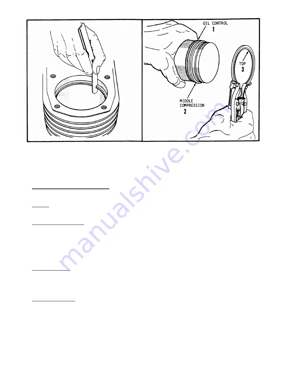
Figure 29 Measuring Piston Ring End Gap
Figure 30 Ring Installation Sequence
connecting rod small end are worn beyond limits, they can be reworked to receive the available .005 or .010
oversize piston pins. In many cases, it may be more advantageous to use a new piston-rod assembly rather than
to rework the old piston boss and connecting rod. A new piston pin should be used when a new connecting rod
is used with the original piston. After checking pin, rod and piston boss to make sure proper clearances are
available, assemble piston to rod with pin (light interference to loose fit) and lock pin with new retainers -make
sure retainers are fully engaged in grooves.
VALVES - VALVE MECHANISM
Carefully inspect valve mechanism parts. Check valves and valve seat area or inserts for evidence of deep
pitting, cracks or distortion. Check clearance of valve stems in guides.
Guides:
To remove, drive guides down into valve chamber and carefully break protruding end until guide is
completely removed. Be careful not to damage block when removing old guide. Use an arbor press to install
new guides --- press to depth stated in Clearance Section.
Valves and Valve Seats:
Consult parts manual for correct valve numbers when replacing valves. Some
applications require special hard-faced valves for both intake and exhaust valves. Exhaust valves are always
hard faced. Intake valve seats are usually machined into block although inserts are used in certain applications.
Exhaust valves seat on special hardened inserts. Seating surfaces should be held as close as possible to 1/32"
width. Seats with more than 1/16" must be reconditioned with 45° and 15° cutters to obtain proper width.
Reground or new valves must be lapped in to provide proper fit. Use a hand valve grinder with suction cup for
final lapping. Lightly coat valve face with "fine" grade of grinding compound then rotate valve on seat with
grinder. Continue grinding until smooth surface is obtained on seat and on valve face.
Valve Clearance:
Valve clearance must be checked after resurfacing and lapping in. Install valves in guides,
rotate camshaft to position where cam has no effect on tappet - hold valve firmly on seat and check clearance
between valve stem and tappet (See Clearance Section).
Adjustable tappets are used on the K241 and K301 engines. Loosen the locking nut, turn adjusting nut in or
out until proper clearance is attained then securely tighten locknut.
CYLINDER HEAD
Blocked cooling fins often cause localized "hot spots" which can result in "blown" cylinder head gaskets.
If gasket fails in area surrounding one of the retaining capscrews, high temperature combustion bases can burn
away portions of aluminum alloy head. If no evidence of this is found, head should be checked for flatness. A
slightly warped head can be resurfaced by simply rubbing it on a piece of sandpaper positioned on a flat
surface. Carefully clean carbon deposits from cylinder head if it is to be reused - use putty knife
or similar
blade to scrape deposits. Be careful not to nick or scratch aluminum, especially in gasket seat area.


