


34
Figure 25 Pulling Bearing Plate
C.
Cylinder bore - If badly scored, excessively worn or tapered or out of round more than .005, reboring if
necessary. Use an inside micrometer to determine amount of wear (See Fits and Clearance Section). If
cylinder bore is not damaged and is within tolerances, only light deglazing may be necessary.
2.
RECONDITIONING - CYLINDER BLOCK
A.
Remove old oil seal from block but do not install new seal until after crankshaft is reinstalled.
B.
Reboring procedure - See Clearance Section for original cylinder bore size. Use an inside micrometer
to measure wear then select nearest suitable oversize of either .010, .020 or .030". Reboring to one of
these oversizes will allow usage of the available oversize piston and ring assemblies. While most
commercially available cylinder bores can be used with either portable drills or drill presses, the use of
a low speed drill press is preferred as it facilitates more accurate alignment of the bore in relation to the
crankshaft crossbore. Reboring is best accomplished at drill speed of about 600 RPM. After installing
coarse stones in hone, proceed as follows:
1.
Lower hone into bore and after centering, adjust so that stones are in contact with walls. Diesel fuel
oil or kerosene can be applied to the stones as a cutting-cooling agent.
2.
With the lower edge of each stone positioned even with the lowest edge of the bore, start drill and
honing process. Move hone up and down while reboring to prevent formation of cutting ridges.
Check size frequently.
3.
When bore is within .0025 of desired size, remove coarse stones and replace with burnishing
stones. Continue with burnishing stones until within .0005 of desired size then use finish stones and
polish to final size.
4.
After reboring, carefully clean cylinder wall with soap and water, then after drying thoroughly,
apply light coat of oil to prevent rust.
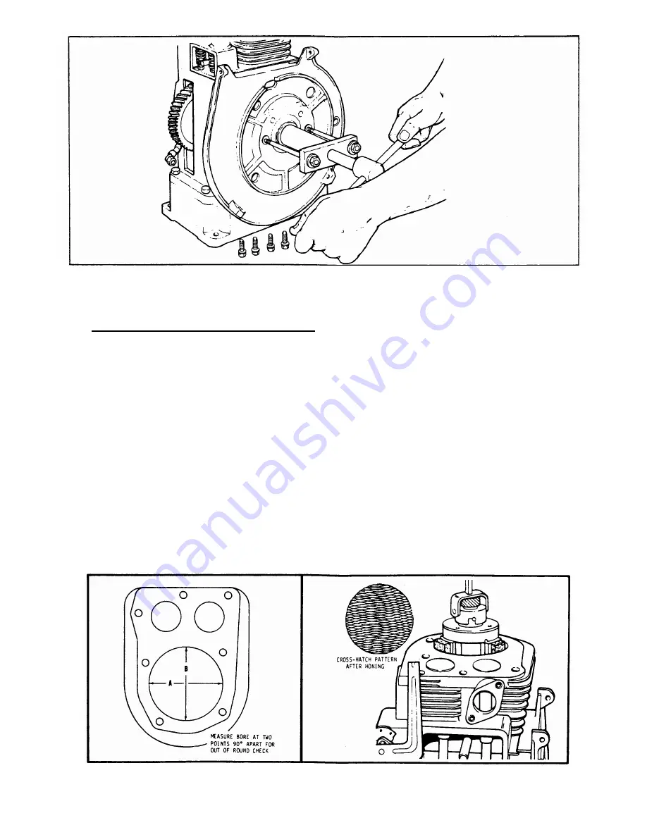
Figure 26 Measuring Cylinder Bore
Figure 27 Honing Cylinder Walls


