39
38
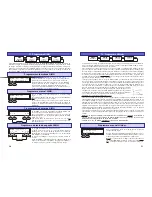
16. Error and warning messages
The charger incorporates a wide range of protective and monitoring systems designed to check the
charger’s functions and monitor the state of its electronics. If any of the unit’s limit values are exceeded,
in some cases the unit’s settings are automatically reduced (e.g. charge or discharge current); in others
the charge process is switched off (e.g. car battery almost flat).
The liquid crystal screen displays the cause of the error. Most error message are self-explanatory, but
you may find the following list useful when fault-finding. The warning message and the audible warning
signal can be switched off by pressing the “
ENTER
” button.
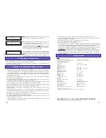
Automatic current limiting
_ _ _ _ _ _ _ _ _ _ _ _ _ _ _ _
_ _ _ _ _ _ _ _ _ _ _ _ _ _ _ _
N i C d - M a n .
0 1 0 : 4 3
1 , 5 0
0 1 7 3 5
2 3 , 4 5
M A X .
_ _ _ _ _ _ _ _ _ _ _ _ _ _ _ _
_ _ _ _ _ _ _ _ _ _ _ _ _ _ _ _
N i C d - M a n .
0 1 0 : 4 3
3 , 7 5
0 1 7 3 5
2 3 , 4 5
* r e a d y *
When a charge / discharge program completes its cycle, the
screen displays the program name alternating with the mes-
sage “
Completed
”. At the same time the integral buzzer sounds,
in accordance with the settings you have made under “Button
click / buzzer”.
If you set a charge / discharge current which the ULTRAMAT
25 cannot deliver because it falls outside its technical limits,
the unit automatically reduces the current to the maximum
possible value. To warn you of this, the screen displays the
charge / discharge current which is actually flowing, alterna-
ting with the warning message “
MAX
”.
Possible causes of an automatic reduction include:
- High cell count combined with high discharge current; the maximum discharge power is 50 Watts.
- Converter power insufficient to produce the selected charge current.
- Overload protection - current reduction protects the unit from overloading.
- Car battery voltage too low to supply the selected charge current.
Pb charge programs:
In the Pb charge programs the screen displays the message “
MAX
” when the charger has automatically
reduced the set charge current because it is too high for the battery on charge.
“Completed” message
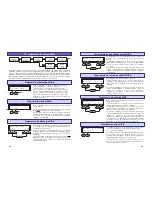
Display of car battery voltage
_ _ _ _ _ _ _ _ _ _ _ _ _ _ _ _
_ _ _ _ _ _ _ _ _ _ _ _ _ _ _ _
N i C d - A u t o
0 1 0 : 4 3
c a r
b a t t .
1 2 , 8 V
The actual car battery voltage can be called up during any
charge / discharge process by pressing the INC and DEC but-
tons
simultaneously
.
Note: the car battery voltage
cannot
be displayed if a charge /
discharge program is not currently active.
DEC
INC
_ _ _ _ _ _ _ _ _ _ _ _ _ _ _ _
_ _ _ _ _ _ _ _ _ _ _ _ _ _ _ _
* * * * * E R R O R * * * * * *
c a r
b a t t .
e m p t y
This warning message is displayed if the voltage of the car
battery falls below the value selected in the program menu
“Low voltage cut-off” in the user settings (11.5 V or 10.8 V).
14. Screen displays
Battery voltage
_ _ _ _ _ _ _ _ _ _ _ _ _ _ _ _
_ _ _ _ _ _ _ _ _ _ _ _ _ _ _ _
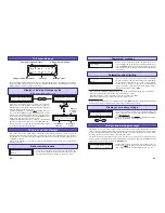
N i C d - M a n .
0 1 0 : 4 3
3 , 7 5
0 1 7 3 5
2 3 , 4 5
Charge / discharge program
Charge / discharge time
Charge / discharge current
Capacity
The essential information relating to the current charge / discharge process is displayed in clear form on
the two-line liquid crystal screen; the screen also indicates that the buzzer is sounding. The previously
displayed values can then no longer be called up.
15. Screen monitor displays
The charger incorporates a wide range of protective and monitoring systems designed to check the
charger’s functions and monitor the state of its electronics. If any of the unit’s limit values are exceeded,
the charge process is switched off. Typical triggers would be excess voltage, excessive temperature or
a depleted car battery.
If any of these problems occur, the liquid crystal screen displays the cause of the error, and the buzzer
sounds to alert you.
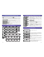
_ _ _ _ _ _ _ _ _ _ _ _ _ _ _ _
_ _ _ _ _ _ _ _ _ _ _ _ _ _ _ _
c y c l .
D
1
0 1 0 : 4 3
1 , 5 0
0 1 7 3 5
2 3 , 4 5
When the cycle program has been started, the screen dis-
plays at top centre the progress of the program: “L” stands for
Charge and “E” for Discharge. The number after the letter indi-
cates the number of the current cycle.
A display of individual cycle data is
only
available when you
have selected the NiCd balancing program, and the cycle in-
formation is only retained until the battery is disconnected, or
until you interrupt the program by pressing the MODE button.
When you do this, the data is reset to “00000”.
Pressing the INC button takes you to a display of the individual
data sets, and each successive press of the INC button swit-
ches to the next set of cycle data. Pressing the DEC button
cycles back through the displayed data.
Display of individual charge cycles
(NiCd balancing program only)
DEC
INC
_ _ _ _ _ _ _ _ _ _ _ _ _ _ _ _
_ _ _ _ _ _ _ _ _ _ _ _ _ _ _ _
C y c l e
1
E : 0 1 0 3 9
L : 0 1 1 7 9
DEC
INC
_ _ _ _ _ _ _ _ _ _ _ _ _ _ _ _
_ _ _ _ _ _ _ _ _ _ _ _ _ _ _ _
C y c l e
1 0
E : 0 1 0 3 9
L : 0 1 1 7 9
Charge /
dischrge
cycle
Charged-in
capacity
Discharged
capacity
_ _ _ _ _ _ _ _ _ _ _ _ _ _ _ _
_ _ _ _ _ _ _ _ _ _ _ _ _ _ _ _
N i C d - M a n .
0 1 0 : 4 3
1 , 5 0
0 1 7 3 5
2 3 , 4 5
T E S T
Measurement process
The charger repeatedly measures the battery during the char-
ge process. During the measurement phases the screen dis-
plays the message “TEST” in place of the charge current.


