


34
Configuration
CRSC Networks
The buttons in the graphic image of the configuration page correspond in number and posi-
tion to the buttons of the actual control panel. (The CP6401 is an exception: the graphic has
a button for the configured destination, but the panel has no such button.)
The ‘Destination Lock’ and ‘Panel Lock’ buttons (both red in the panel graphic) are not con-
figurable for any panel.
7 Save the remote panel configuration.
Click ‘Update Panel’ to transfer the remote panel configuration to the selected remote panel
module. (The transfer takes about one minute.)
You can also click ‘Save to File . . . ’ at the bottom of the page to save a copy of the remote
panel configuration to your file system. At any time you can click ‘Read from File . . .’ to
retrieve a saved configuration.
It is a good idea to save all your remote panel configurations in case your remote panel
modules are ever reset to their factory-default state.
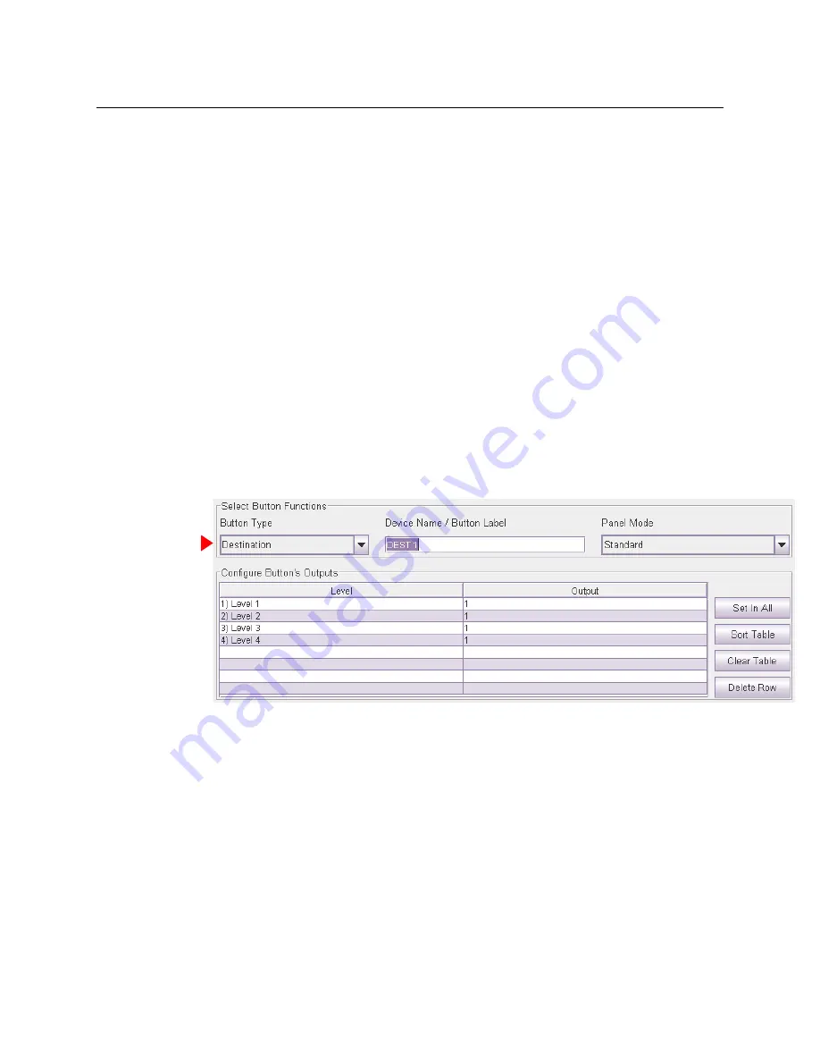
Defining Destination Buttons
To configure a button as a destination button:
1 Click on the image of the particular button you want to configure.
2 Choose ‘Destination’ from the ‘Button Function’ drop-down list. The ‘Configure Button’s Out-
puts’ table appears. It has 8 rows. Each row can represent a level/output pair.
3 Enter (level, output) pairs on rows of the table. Click on ‘Level’ field to select a level from
drop-down list. Click in the ‘Output’ field to enter an output number manually.
You can use the context menu to edit the destination table.
You can drag-and-drop levels from the ‘Levels’ table to the destination table.
4 Optionally enter a mnemonic in the ‘Device Name / Button Label’ field.
The purpose of the table is to identify the output ports that compose the destination.
The outputs you specify are
in the range you specified as the “Controller Outputs”
in the ‘Router
Levels’ page. For example, suppose a 32×32 AES router is divided into 4 equal partitions:
Level A = outputs 1–8,
Level B = outputs 9–16,
Level C = outputs 17–24,
Level D = outputs 25–32 where each level’s
controller outputs
start counting at 1.
Summary of Contents for CR6400 Family
Page 1: ...CR6400 Family Digital Compact Routers and Control Panels User s Guide UG0078 01 30 Sep 2014 ...
Page 32: ...22 Installation Testing ...
Page 50: ...40 Configuration NV9000 Networks ...
Page 84: ...74 CRSC Network Operation Performing Level Selection ...
Page 108: ...98 Index ...
Page 110: ......


