24
Configuration
Stand-Alone Routers
The Physical Inputs and Output Connections
The 3Gig and AES I/O cards have 32 DIN 1.0/2.3 connectors. (We call them “coax” connectors.) All
the inputs are on the left and all the outputs are on the right. The alarm and power LEDs (and
the card label) separate the two sections of a card.
In the 4 card slots, the inputs are numbered 1–64 as slots go from the top of the router to the
bottom. The same is true of the outputs.
Connect input devices and output devices to the router according to the requirements of your
system.
See
Video Specifications
on page 82 for cable length limits.
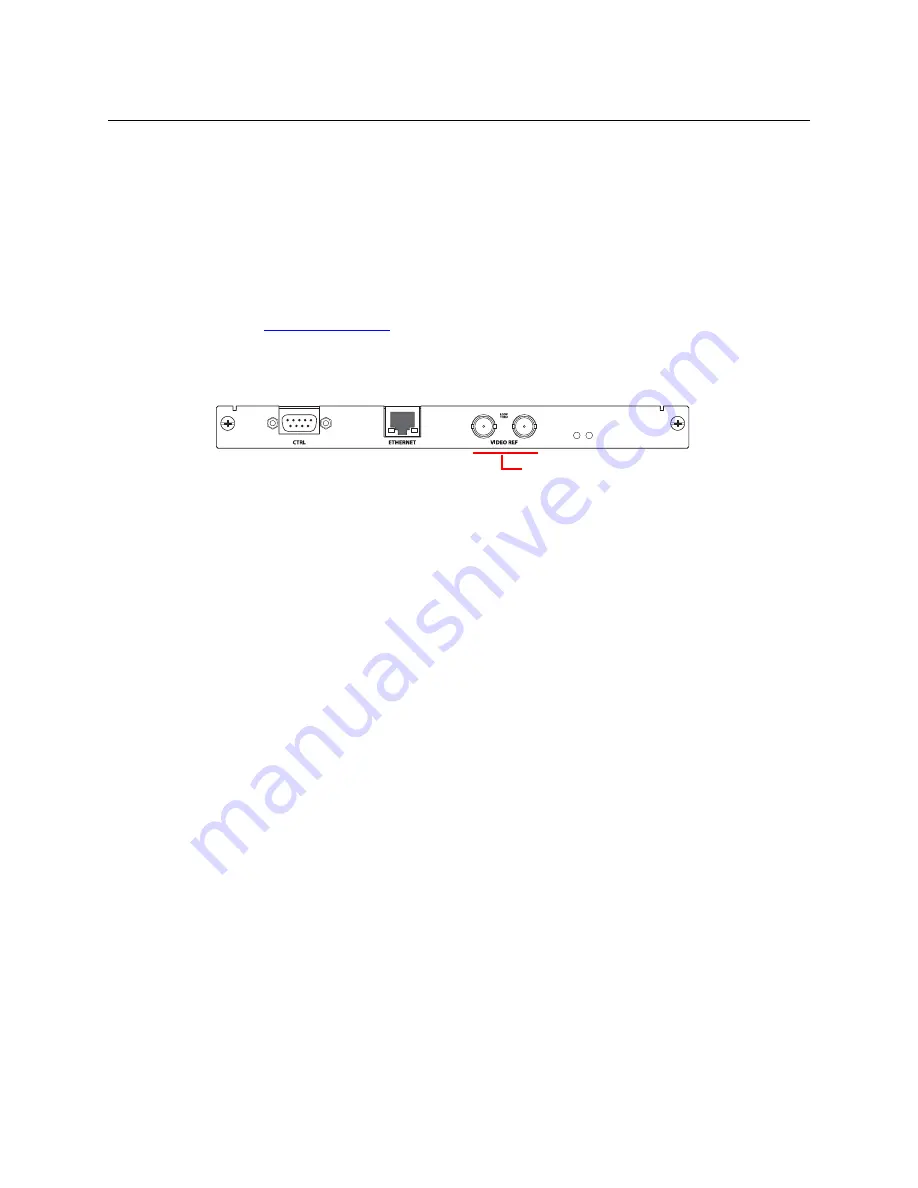
External Video Reference
The reference connectors are a pair of 75
W
BNCs, loop-through, on the control card:
Connect your video reference input to either video reference connector on the rear of the
router. Use the other video reference connector to feed the reference signal to another device.
Terminate the reference signal (or chain of reference signals) using a 75
W
terminator.
The Rotary Switch
A single stand-alone router does not use its 16-position rotary switch setting (useful only in a
network) but you should set it to a non-zero position in any case. (When the rotary switch is
zero, the router reverts to its factory-default state at power-up.)
When a control panel is mounted on a router, it conceals the rotary switch. You must remove the
control panel when you are setting the rotary switch.
Every time you change the rotary switch position, power-cycle the router.
Button Legends
You can label the control panel buttons. Use a desktop publishing program to create your own
button legends. The legends should be transparent and no larger than 0.40”× 0.40” (10mm
square). A 3/8” (9.5mm) square insert will allow a little clearance. The clear plastic material used
for overhead transparencies is suitable for printing legends.
To apply a label to a button, pull the clear plastic cap from the button, insert the label in the cap,
and replace the cap. We recommend that you not use adhesive.
Button legend templates (in Word,
®
Illustrator,
®
and Freehand
®
formats) are available on the
documentation and software CD (SB0033) you received with your CR6400 product(s). Simply
type (or draw) the legends you want, print the page on transparent film, and cut the buttons
apart.
Note: selection buttons of the CP6464 represent both sources and destinations. Therefore
button legends must accommodate both source mnemonics and destination mnemonics.
To fit on the button and be legible, your mnemonics must be relatively short.
Video Reference
Summary of Contents for CR6400 Family
Page 1: ...CR6400 Family Digital Compact Routers and Control Panels User s Guide UG0078 01 30 Sep 2014 ...
Page 32: ...22 Installation Testing ...
Page 50: ...40 Configuration NV9000 Networks ...
Page 84: ...74 CRSC Network Operation Performing Level Selection ...
Page 108: ...98 Index ...
Page 110: ......


