background image

2-7

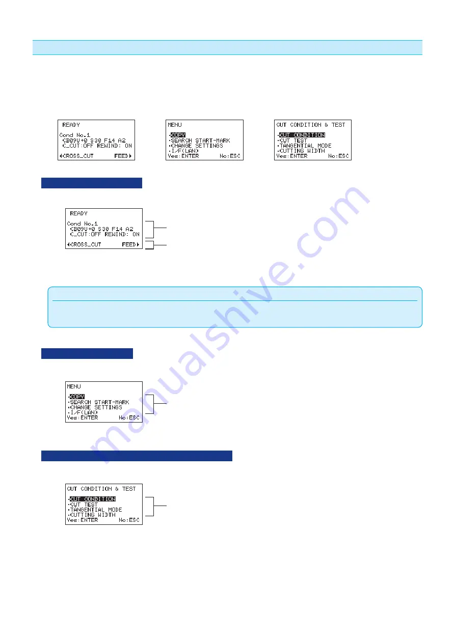
Reading the Screen (LCD)

,QIRUPDWLRQUHÁHFWLQJWKHVWDWXVZLOOEHGLVSOD\HGLQWKHVFUHHQRIWKHFRQWUROSDQHO

Name of the button or corresponding function is displayed on the screen when a function is allocated to the 
button on the control panel. Button name will be displayed in reverse when the item is selected.

READY screen

(READY)

MENU screen

(MENU)

CUT CONDITION & TEST screen

(COND/TEST)

READY screen (READY)

The following items are displayed in the basic screen (READY).

Display the current cutting conditions.

CROSS CUT
Media feed (FEED)

The Condition No. (Cutting conditions) that has been set is displayed.

Supplement

 In this manual, this basic screen is referred as READY status.

,QWKLV5($'<VWDWXV\RXFDQVHWWKHFXWWLQJDQGFRPPXQLFDWLRQFRQGLWLRQVE\SUHVVLQJ>0(18@RU>&21'7(67@NH\

MENU screen (MENU)

7RGLVSOD\WKH0(18VFUHHQXVHGWRVHWWKHYDULRXVFRQGLWLRQVSUHVV>0(18@NH\

Set the various conditions.

7KHVHOHFWHGLWHPLVKLJKOLJKWHG3UHVV>(17(5@NH\WRGLVSOD\WKHVHWWLQJVFUHHQUHODWHGWRWKHKLJKOLJKWHGLWHP

CUT CONDITION & TEST screen (COND/TEST)

7RGLVSOD\WKHVHWWLQJVFUHHQXVHGWRVHWWKHFRUUHVSRQGLQJFRQGLWLRQVSUHVV>&21'7(67@NH\

Set the cutting condition and cutting 
test, etc.

Summary of Contents for LABERLROBO DLC1000

Page 1: ...86 5 6 0 18 MANUAL NO DLC1000 UM 151 www delinit by...

Page 2: ......

Page 3: ...fore reading the Manual DANGER This category provides information that if ignored is highly likely to cause fatal or serious injury to the operator WARNING This category provides information that if i...

Page 4: ...posed to water rain or snow 6XFK DFWLRQ PD UHVXOW LQ HOHFWULFDO VKRFN RU D UH KD DUG due to current leakage Even when the machine is stopped it may suddenly start operating if it receives data so be s...

Page 5: ...G Handle cutter blades with care Avoid direct contact with the cutter blade Touching the blade with your bare hand may cause injury During a cutting operation keep away from the cutter blade Do not us...

Page 6: ...he machine in an excessively dusty or humid location Such locations may impair the performance of the machine Do not use or store the machine in a location exposed to direct sunlight or the direct dra...

Page 7: ...d impair the machine s cutting quality Move the pen carriage slowly when moving it manually in order to load the medium or for other reasons Moving it quickly may damage the machine Run a test cut whe...

Page 8: ......

Page 9: ...ion of Graphtec Corporation 7KH VSHFL FDWLRQV DQG RWKHU LQIRUPDWLRQ WKLV PDQXDO DUH VXEMHFW WR FKDQJH ZLWKRXW QRWLFH 3 While every effort has been made to supply complete and accurate i nformation abo...

Page 10: ...RXUVHOI ZKHQ KDQGOLQJ WKH FXWWHU SHQ Blade tip Return used blades to the accessory cutter blade case and throw them all out together when the whole case has EHHQ OOHG Cutter Pen The tip consists of a...

Page 11: ...range of movement Do not place any foreign objects in or near these areas either If your hands hair clothing or the like get caught in or wrapped around moving parts you may be injured and the machine...

Page 12: ...uminum evaporator coil mat such as the FNS KESHI N25 Apply strong adhesion for adhesive materials Usage Environment When printing is carried out in a hot and humid environment this may cause the label...

Page 13: ...s and can radiate radio frequency energy and if not installed and used in accordance with the instruction manual may cause harmful interference to radio communications Operation of this equipment in a...

Page 14: ...0 A Table 2 200 V to 240 V Power Supply Voltage Range 3OXJ RQ JXUDWLRQ Plug Type Supply Voltage Selector Settings Reference Standards Power Cable Europe 250 V 10 A 200 V CEE 7 VII IEC320 CEE13 TYPE H0...

Page 15: ...FWV IV Usage Environment IV Media IV Consumable Parts IV After Use IV Prior to use V WARNING V FEDERAL COMMUNICATIONS COMMISSION RADIO FREQUENCY INTERFERENCE STATEMENT V USE SHIELDED CABLES V Selectin...

Page 16: ...the slitter 2 51 2 10 COND TEST Key 2 55 Screen Flow Through COND TEST Key 2 55 2 11 Select the Tool Conditions 2 56 LCD Display 2 56 Selecting the Tool Condition No 2 56 Setting Tool Condition 2 58 S...

Page 17: ...WEIGHT 4 17 4 12 BAR CODE 4 19 If the bar code does not match 4 21 4 13 FRAME CUT 4 22 4 14 OFFSET FORCE 4 24 4 15 DISTANCE ADJ 4 25 4 16 LENGTH UNIT 4 27 Chapter 5 Setting the Interfaces 5 1 SETTING...

Page 18: ...ional Accessories A 4 Supplies Laminate A 4 Supplies Paper core for winding up A 4 Recommended initial supply kit A 4 Supplies Cutter A 5 Supplies Consumable Items A 5 Optional Accessories Flange Set...

Page 19: ...1 1 Chapter 1 Product Summary This chapter explains how to connect this device your computer PRODUCT SUMMARY 1 1 Checking the Accessories 1 2 Nomenclature 1 3 Connecting to the Computer www delinit by...

Page 20: ...DQJH FROODU 0DUNHG JURRYH Separator flange collar 1 set DPLQDWH ZLQGHU EREELQ 6HSDUDWRU DQJH FROODU 6HSDUDWRU DQJH FROODU 1RW PDUNHG Separator flange collar 1 set Dancer roller 1 2 2 set Attachments...

Page 21: ...ng this machine via network I F 5 Control panel Carry out operations and various settings 6 Cutter unit Cuts stenciling frame cutting media 7 Set lever When loading the media to the cutting part raise...

Page 22: ...e location to set the roll holder 5 Slitter unit This is used to width cut longitudinal cut the roll paper 6 Cross cutter unit XWWHU XVHG IRU FURVV FXWWLQJ KRUL RQWDO FXWWLQJ PHGLD 7 Ejection roller T...

Page 23: ...or turning power on again H VXUH WR FRQ UP WKDW WKH SRZHU VZLWFK LV LQ WKH 2II position When the power switch is in the Off position you can turn it On by turning the emergency stop switch clockwise u...

Page 24: ...ler to UHOHDVH DQG WKH PHGLD 4 Tool holder Holds the cutter pen or plotting pen and moves it up or down 5 Tool carriage Moves the cutter pen or plotting pen across the media during cutting 6 Grit roll...

Page 25: ...Select which port to use according to the requirements of your application software and or which of your computer s interface ports are available for use Please install driver software before connect...

Page 26: ...terface 2 Connect using the connection cable between the PC and this machine Connecting With USB Interface Computer USB cable Supplied with the cutter unit Connecting With Network Interface Computer N...

Page 27: ...Setting the Label Material Media When using the separator weeding When the winding roll holder is used When the winding roll holder is not used 2 6 Aligning the Push Rollers 2 7 Using the Laminate 2...

Page 28: ...lade length needs to be adjusted to perform optimal cut Perform few test cuts and set the optimal blade length CAUTION To avoid bodily injury handle cutter blades with care It may result in damaging t...

Page 29: ...2 3 Blade Application and Features Select the optimal cutter blade and media to be cut Refer to the Cutter Blade Manual CAUTION To avoid bodily injury handle cutter blades with care...

Page 30: ...turned on or whenever the tool is moving There are two types of tool holders When setting the cutter plunger in the tool holder please be careful to the set position It is explained here using cutter...

Page 31: ...completely touches the upper part of the holder Cutter plunger can not to be set in forward Set on the tool holder Backward Tool holder Tool holder Flange Bracket to hold tool 3 Make sure that the to...

Page 32: ...TEST screen with the cutting conditions and test menus Cross Cut URVV FXW WKH PHGLD LQ WKH 5 VFUHHQ 7KH FRQ UPDWLRQ VFUHHQ LV GLVSOD HG 7KH PHGLD LV FURVV FXW E SUHVVLQJ 17 5 NH Media Feed The label...

Page 33: ...ent cutting conditions CROSS CUT Media feed FEED The Condition No Cutting conditions that has been set is displayed Supplement In this manual this basic screen is referred as READY status Q WKLV 5 VWD...

Page 34: ...The number of current cuts is displayed during copy Current number Total number Display the number of current cuts Current number Total number Notes on the media feed KHQ WKH ODEHO PDWHULDO PHGLD LV...

Page 35: ...turn on the power of the machine Supplement KHQ SHUIRUPLQJ WKH SRZHU F FOH SOHDVH WXUQ RQ DIWHU PRUH WKDQ VHFRQGV KDV HODSVHG I VXI FLHQW WLPH KDV QRW HODSVHG WKH XWWHU may not be reset properly Oper...

Page 36: ...the label material media is not loaded or when the set lever on the cutter unit is lowered the following message is displayed after the version is displayed 3 Turn on side the power of the machine Th...

Page 37: ...ter diameter 210 mm or 200 m roll For the relationship of the label material and the laminate material and FXWWLQJ DUHD UHIHU WR WKH JXUH EHORZ Cutting area Label material media width 70 to 186 mm It...

Page 38: ...DQJH 7KH DQJH ZLWK ORQJHU VKDIW LV WKH UROO KROGHU DQJH The shape of roll holder shaft is similar to those of laminate holder shaft Longer shaft is the roll holder shaft KHQ WKH DQJH LQJ VFUHZ LV QRW...

Page 39: ...QRW be touched ODQJH LQJ VFUHZ ODQJH LQJ VFUHZ Roll holder shaft Flange B Flange A Pin 3 WWDFK WKH ODQJH WR WKH UROO KROGHU VKDIW 6HW LQ WKH GLUHFWLRQ DQJH LQJ VFUHZV VLGH LQ ZKLFK WKHUH is a pin of t...

Page 40: ...RVHQ WKH DQJH LQJ VFUHZ RI ODQJH E WXUQLQJ LW counterclockwise Attach the Flange A to the roll holder shaft Media Flange A ODQJH LQJ VFUHZ 5 7XUQ WKH PHGLD LQJ NQRE RI ODQJH FORFNZLVH WR WKH SDSHU FRU...

Page 41: ...A and the media KDYH EHHQ HG Move the label material media until it contacts the pin Flange A Media Pin Flange A Media 8 Push the Flange B so that there is no gap between the paper core and Flange B...

Page 42: ...DQJH LQJ VFUHZV WLPHV 3OHDVH GR QRW ORRVHQ WKH DQJH LQJ VFUHZV WRR PXFK 7KH SLQ ZLOO QR ORQJHU KLW LQ 6WHS Flange A ODQJH LQJ VFUHZ 2 Move the label material media to the direction of the pin in a sta...

Page 43: ...2 17 3 LooVHQ WKH DQJH LQJ VFUHZV Push the Flange B so that there is no gap between the paper core and Flange B ODQJH LQJ VFUHZ Flange B Flange B 4 RRVHQ WKH DQJH LQJ VFUHZ ODQJH LQJ VFUHZ Flange B...

Page 44: ...Temporarily place the roll holder on the front part of the roll stocker and make sure that it is in straight Roll stocker cover Temporarily place the roll holder on the front part and make sure that...

Page 45: ...W RXU QJHUV SLQFKHG RU VWXFN RQ WKH JHDUV UROOHUV RU RWKHU PRYLQJ SDUWV ZKHQ ORDGLQJ WKH PHGLD Deviations and errors may result if the roll holder shaft is misaligned when the cutting operation starts...

Page 46: ...sion unit and ejection roller lever open Press roller lever Separator suppression unit Brush part Ejection roller lever Set lever Supplement 7KH IROORZLQJ JXUH VKRZV WKDW WKH SUHVV UROOHU OHYHU VHW OH...

Page 47: ...Ejection roller Dancer roller 1 Laminate winder bobbin Laminate holder Dancer roller 2 Roll holder Roll holder 2 Pull out the media in a state which the media is set in the roll stocker Insert the med...

Page 48: ...2 22 3 Pass through the lower side of the press roller Press roller 4 Pass through the cutter unit Align the position of the push roller Refer to 2 6 Setting the Push Roller Push roller...

Page 49: ...2 23 5 Pull out it from the cutter unit 6 Pass through the lower side of the separator suppression unit Brush part Lower the separator suppression unit Brush part Separator suppression unit Brush part...

Page 50: ...arator suppression unit Brush part pull out the media about 30 cm Approx 30 cm When the separator weeding is used refer to When using the separator weeding described below When the separator weeding i...

Page 51: ...depends on the cut pattern 7KH VKDSH RI VHSDUDWRU ZLQGHU EREELQ LV VLPLODU WR WKRVH RI ODPLQDWH ZLQGLQJ EREELQ LUHFWLRQ WR WLJKWHQ WKH VHSDUDWRU DQJH FROODU DWWDFKHG WR WKH VKDIW LV GLIIHUHQW REELQ WK...

Page 52: ...H FROODU RI WKH VHSDUDWRU ZLQGHU EREELQ WKH WLJKWHQLQJ GLUHFWLRQ ZKHQ LQVWDOOLQJ LV FRXQWHUFORFNZLVH direction and the loosening direction when removing is clockwise direction Please be careful when y...

Page 53: ...seal of the media Pass the peeled seal through the lower side of the center shaft of the separator suppression unit Brush part and pull it on the upper side Then paste it on the separator winding bobb...

Page 54: ...bar of the separator unit to separator winding bobbin so as to extend along the separator winding bobbin Presser bar 1 2 The installation of separator unit is complete 8 Pass the media through the lo...

Page 55: ...accordance with the media position seal When the cross cut is used drop the media down without passing through the slitter part Refer to 2 8 Using the Cross Cut Media position seal Cross cutter 10 Pu...

Page 56: ...loosen the two screws and then move both screws to outside edges When the slitter is used refer to 2 9 When Using the Slitter Screw 12 Set the media on the inlet of the slitter Pull out the media back...

Page 57: ...ed 14 HHG WKH PHGLD E SUHVVLQJ NH Media Feed Pull out the media about 30 cm backward from the slitter Then tighten the screw of slitter Screw 15 Pull out the media from the slitter backward When the w...

Page 58: ...ll holder corresponding to two sets Open the winding stocker cover Remove the roll holder to be used After setting the winding roll holder go to Step 17 When the winding roll holder is used 1 RRVHQ WK...

Page 59: ...Shaft Flange B Set the Flange B at the position where it stops with the screw 7LJKWHQ WKH DQJH LQJ VFUHZV WHPSRUDULO WLJKWHQ ODQJH LQJ VFUHZ temporarily tighten Screw Flange B When winding the media w...

Page 60: ...QJH E WXUQLQJ LW counterclockwise Attach the Flange A to the roll holder shaft Paper core Flange A ODQJH LQJ VFUHZ 4 L WKH SDSHU FRUH E WXUQLQJ WKH PHGLD LQJ NQRE RI ODQJH FORFNZLVH 0HGLD LQJ NQRE 5 7...

Page 61: ...ia might be folded or creased Typically the media must be wound using the winding roll holder 17 Set the roll holder in the winding stocker Close the winding stocker cover When the media to be wound i...

Page 62: ...roll holder GMXVW WKH DQJH SRVLWLRQ WR DOLJQ WR WKH HMHFWHG PHGLD DQG WKHQ WLJKWHQ WKH DQJH LQJ VFUHZ Media Paper core Tape 19 Adjust the position of the push roller in cutter unit Refer to 2 6 Aligni...

Page 63: ...r lever Ejection roller lever Set lever Supplement 7KH IROORZLQJ JXUH VKRZV WKDW WKH SUHVV UROOHU OHYHU VHW OHYHU VHSDUDWRU VXSSUHVVLRQ XQLW HMHFWLRQ UROOHU OHYHU DUH VHW FORVHG RU opened Opened state...

Page 64: ...and 2 when setting them Dancer roller 1 Heavy Dancer roller 2 Light Dancer roller 1 Dancer roller 2 22 When the following screen is displayed set the dancer rollers in accordance with the message and...

Page 65: ...t rollers Position the push rollers within the grit roller position guides ensures that they are above the grit rollers Push roller Grit roller Grit roller position guide It isn t on the grit roller I...

Page 66: ...DQJH LV VLPLODU WR WKH UROO KROGHU DQJH 6PDOOHU DQJH LV D ODPLQDWH KROGHU DQJH The shape of laminate winder bobbin is similar to those of separator winding bobbin The bobbin that is not marked groove...

Page 67: ...1 2 2 RRVHQ WKH DQJH LQJ VFUHZ RI WKH ODPLQDWH KROGHU E WXUQLQJ LW FRXQWHUFORFNZLVH Remove the DQJH I WKH DQJH LQJ VFUHZV WRXFKHV WKH SLQ RI VKDIW ORRVHQ WKH DQJH LQJ VFUHZV XQWLO LW FDQQRW EH touche...

Page 68: ...WLRQ DQJH LQJ VFUHZV VLGH LQ ZKLFK WKHUH LV D SLQ RI WKH VKDIW Shaft Flange Pin ODQJH LQJ VFUHZ 6HW WKH DQJH DW WKH SRVLWLRQ ZKHUH LW VWRSV ZLWK WKH VFUHZ 7LJKWHQ WKH DQJH LQJ VFUHZV WHPSRUDULO WLJKWH...

Page 69: ...edia with revolute RRVHQ WKH DQJH LQJ VFUHZ RI DQJH E WXUQLQJ LW counterclockwise WWDFK WKH DQJH WR WKH VKDIW Laminate material Flange ODQJH LQJ VFUHZ 3XVK WKH DQJH VR WKDW WKHUH LV QR JDS EHWZHHQ WKH...

Page 70: ...2 44 5 7LJKWHQ WKH DQJH LQJ VFUHZ ODQJH LQJ VFUHZ ODQJH LQJ VFUHZ 6 Set the laminate holder and then close the cover 2 1 Grasp this part of roll holder...

Page 71: ...ate winder bobbin 8 Remove the VHSDUDWRU DQJH FROODU E WXUQLQJ LW FRXQWHUFORFNZLVH DQG WKHQ UHPRYH WKH DQJH 6HSDUDWRU DQJH FROODU Flange 9 6HW WKH SDSHU FRUH VROG VHSDUDWHO DQG WKHQ DWWDFK WKH DQJH 7R...

Page 72: ...inate winder bobbin and then close the cover 2 1 11 Pass through the laminate material under the tension bar and pull out it about 15 cm Peel off the tip portion of the adhesive seal of laminate Tensi...

Page 73: ...te to the press roller Laminate adhesive seal Backing sheet 13 Attach the backing sheet to the laminate winder bobbin by using tape If the backing sheet of laminate material is loosed rewind it by tur...

Page 74: ...that has weeded by the separator The label material with the backing sheet or the label that stuck a laminate material may not be cut off completely At this time the glue of the label material is att...

Page 75: ...paper is folded or creased may occur Supplement It is not possible to adjust the position of slitter in a state in which the label material has been set When the label material has been set set the sl...

Page 76: ...eding direction Slitter Edge cut Edge cut Center cut OK OK OK NG NG NG Not use a slitter Both edges cut Both edges and center cut One edge cut One edge cut Only center cut V VKRZQ LQ WKH JXUH EHORZ VH...

Page 77: ...2 51 When using the slitter 1 Pull out the media about 30 cm in front of the slitter Fold around of about 5 to 10 cm from the tip of the media Approx 30 cm Approx 5 to 10 cm...

Page 78: ...screw before passing through the media the media may not be able to set correctly Screw 3 Set the media on the inlet of the slitter in a state which the screw is loosened and the tip of media is fold...

Page 79: ...Path CAUTION Please be careful there is no slack in the media between the cross cutter and slitter The media might not be able to successfully feed when there is slack Slack When there is slack in th...

Page 80: ...backward from the slitter to use the winding holder Approx 60cm Set the winding roll holder referring to Step 16 in Feed the label material media described above It is not possible to wind the only o...

Page 81: ...e media CUT TEST Perform the cut test TANGENTIAL MODE Set Tangential Mode thick media CUTTING WIDTH Display the cutting area width Screen Flow Through COND TEST Key 21 7 67 17 5 17 5 2 17 5 3 17 5 Ope...

Page 82: ...cting the Tool Condition No Eight settings 1 to 8 as the cutting condition can be stored Settings can be changed in accordance with the label material 8 types to be used Operation 1 3UHVV WKH 21 7 67...

Page 83: ...UH SUHVVLQJ 17 5 key returns to the READY screen without changing the settings 4 RQ UP WKH VHWWLQJ DQG SUHVV WKH 17 5 NH Setting will be set and it will return to CUT CONDITION TEST screen 5 3UHVV WKH...

Page 84: ...CCELERATION CAUTION It may result in damaging the cutter blade or the cutting mat if the blade is extended too much Make sure the blade length is set less than the thickness of the media Tool Conditio...

Page 85: ...low as possible but that still leaves faint traces on the backing sheet Set the SPEED and ACCELERATION values as low as possible Supplement Weeding refers to the removal of unwanted areas from the ba...

Page 86: ...OSITION keys to select the CUT CONDITION The selected item is highlighted Then press 17 5 NH Cond No selection screen is displayed 3 Press the POSITION keys to select the tool Supplement 3UHVVLQJ WKH...

Page 87: ...lected item is highlighted Then press 17 5 NH Cond No selection screen is displayed 3 Press the POSITION keys to select the TOOL OFFSET Supplement What is the Offset It will adjust the difference betw...

Page 88: ...eys to select the CUT CONDITION The selected item is highlighted Then press 17 5 NH Cond No selection screen is displayed 3 Press the POSITION keys to select the SPEED Supplement Settable range is 1 t...

Page 89: ...select the CUT CONDITION The selected item is highlighted Then press 17 5 NH Cond No selection screen is displayed 3 Press the POSITION keys to select the FORCE Supplement Settable range is 1 to 31 4...

Page 90: ...he selected item is highlighted Then press 17 5 NH Cond No selection screen is displayed 3 Press the POSITION keys to select the ACCEL Supplement Settable range is 1 to 3 When the value is reduced the...

Page 91: ...ly At this time the glue of the label material is attached to the blade or the failure of the cross cut section may be caused Please do not cut other than the backing sheet When set to ON used the win...

Page 92: ...d to the blade or the failure of the cross cut section may be caused Please do not cut other than the backing sheet When set to ON used the rewind function is disabled automatically Operation 1 3UHVV...

Page 93: ...E2 Operation 1 3UHVV WKH 21 7 67 NH LQ 5 VWDWXV CUT CONDITION TEST screen is displayed 2 Press the POSITION keys to select the CUT CONDITION The selected item is highlighted Then press 17 5 NH Cond No...

Page 94: ...ed below Setting range 0 0 to 0 9 mm Operation 1 3UHVV WKH 21 7 67 NH LQ 5 VWDWXV CUT CONDITION TEST screen is displayed 2 Press the POSITION keys to select the TANGENTIAL MODE The selected item is hi...

Page 95: ...to 0 9 mm 6 Press the POSITION keys to increase or decrease the setting value 7 RQ UP WKH VHWWLQJ DQG SUHVV WKH 17 5 NH Setting will be set and it will return to CUT CONDITION TEST screen 8 3UHVV WKH...

Page 96: ...Tangential emulation is a control method to precisely cut corners where two straight lines meet See below With the tangential emulation the blade is advanced so it will overcut at the corners before r...

Page 97: ...media Media Blade Supplement Blade length can be changed by spinning the adjustor on the blade Spinning it in the A direction pushes it out while spinning it in the B direction pulls it in One scale u...

Page 98: ...nd repeat the test cutting until the optimal settings are achieved Cutting Test Here you can either cut one test pattern based on the current values or do Four tests with 1 values added To make 1 cut...

Page 99: ...Q WKH FXWWHU EODGH 7 3UHVV 17 5 NH Only one test cut pattern is cut 8 3UHVV WKH 17 5 NH DIWHU FRPSOHWLRQ The CUT TEST screen is displayed 9 3UHVV WKH 6 NH It will return to READY screen When Cutting t...

Page 100: ...Supplement It is impossible to change to the start position by operating the POSITION keys 5 3UHVV WKH 17 5 NH CAUTION 3UHVVLQJ 17 5 NH DFWLYDWHV WKH WRRO carriage Take care to ensure that you do not...

Page 101: ...and rectangle Refer to Setting Tool Condition and adjust the offset value if the corner is not cut properly or if it is cut too much Adjustment for Half Cutting Supplement Refer to Adjusting the Blad...

Page 102: ...action and then the READY screen is displayed KHQ 6 NH LV SUHVVHG LQ WKH PLGGOH RI WKH FXW WKH ODEHO WKDW KDV QHYHU EHHQ FXW LV QRW FXW SURSHUO After stopping the operation if you want to do it again...

Page 103: ...V WKH 21 7 67 NH LQ 5 VWDWXV CUT CONDITION TEST screen is displayed 2 Press the POSITION keys to select the CUTTING WIDTH The selected item is highlighted Then press 17 5 NH 7KH ZLGWK RI FXWWLQJ DUHD...

Page 104: ......

Page 105: ...3 1 Chapter 3 Driver Software This chapter explains the driver software PRODUCT SUMMARY 3 1 Driver Software 3 2 Driver Software Operation...

Page 106: ...he media that is output from the DLP1000 we strongly recommend that the media is cut by using the cutter output function of DLP1000 This driver software can be run on Windows Vista 7 8 8 1 When using...

Page 107: ...e Operation This is a description with regard to the driver software use when printing label data created in the application software etc The display screens are different in each application software...

Page 108: ...A5 A6 A7 4in x 3in 4in x 6in 6in x 4in 6in x 8in 8VHU GH QDEOH VL H WR KHQ WKH SDJH VL H LV GH QHG RX FDQ UHJLVWHU D IUHH VL H E FKDQJLQJ WKH GH QLWLRQ name 7KH PD LPXP VL H LV PP Mirror Used to cut t...

Page 109: ...icking Setting the Color will be displayed You can then choose from the basic colors or add a new one through Add to Custom Colors The allowable value range for a given color is set as 50 as default A...

Page 110: ...rter than this length and does not output them The settings range is 0 1 mm 5 0 mm Treat as same line if gap is 6SHFL HV WKH GRW JDS ZKLFK LV DFFHSWDEOH DV VDPH OLQH GDWD Depending on the application...

Page 111: ...When the Power is Turned On 4 2 Display During Processing 4 3 Display During Feeding Media 4 4 Menu Items 4 5 COPY ENDING FEED 4 6 SEARCH START MARK 4 7 CHANGE SETTINGS 4 8 NUMBER OF POINTS 4 9 SENSIN...

Page 112: ...creen is displayed as shown below 17 5 READY Screen READY The following items are displayed in the READY screen Display the current cutting conditions CROSS CUT Media feed FEED The Condition No Cuttin...

Page 113: ...KH PXOWLSOH QXPEHU KHQ FXW ZLWK WKH UHFHLYHG GDWD DQG WKH PXOWLSOH QXPEHU VSHFL HG Display the number of cuts Current number Total number Display during copying When copying Display the number of copi...

Page 114: ...played during feeding The following is displayed when the Media Feed key is pressed in the READY screen Feed menu When ENTER key is pressed at the same time in this status the media is fed even if you...

Page 115: ...r of copies SEARCH START MARK The START MARK is searched You can check the cut start position CHANGE SETTINGS Change the settings in this machine DLC1000 I F LAN Set the LAN interface Required when th...

Page 116: ...be output the following is displayed 3UHVVLQJ 6 NH 5 7851 UHWXUQV WR previous screen 3 Press the POSITION keys to select COPY The item LV KLJKOLJKWHG 7KHQ SUHVV 17 5 NH COPY screen is displayed Suppl...

Page 117: ...is fed to the ejection part Feeding operation approx 1 m is executed After completing the cutting operation with the cutter unit it is used to eject the data that is between to the cutter unit and cro...

Page 118: ...as this function is set To avoid injury to yourself keep your hands face and other obstacles out of the vicinity of any moving parts 2 Press the POSITION keys to select SEARCH START 0 5 7KH LWHP LV KL...

Page 119: ...OFFSET FORCE DISTANCE ADJ Distance Adjustment and LENGTH UNIT Operation 1 3UHVV WKH 0 18 NH LQ 5 VWDWXV MENU screen is displayed 2 Press the POSITION keys to select CHANGE 6 77 1 6 7KH LWHP LV KLJKOLJ...

Page 120: ...of data start point origin point 3POINT For 3POINT adjustment the axis is adjusted based on the three registration marks of the origin X axis direction and Y axis direction OFF The Axis is adjusted ba...

Page 121: ...KHQ SUHVV 17 5 key NUMBER OF POINTS screen is displayed Supplement 3UHVVLQJ 6 NH 12 UHWXUQV WR SUHYLRXV screen without changing the settings 5 Press the POSITION keys to set the number of registration...

Page 122: ...tion mark will be improved When the NORMAL is set to the ISM the reading time of registration mark reading takes longer than NORMAL Operation 1 Press the MENU key in READY status MENU screen is displa...

Page 123: ...anging the settings 5 Press the POSITION keys to set the sensing speed Settable sensing speed as SENSING SPEED are NORMAL and ISM 6 RQ UP WKH VHWWLQJ DQG SUHVV WKH 17 5 NH Setting will be set and it w...

Page 124: ...d always in the same direction Operation 1 3UHVV WKH 0 18 NH LQ 5 VWDWXV MENU screen is displayed 2 Press the POSITION keys to select CHANGE 6 77 1 6 7KH LWHP LV KLJKOLJKWHG 7KHQ SUHVV 17 5 key CHANGE...

Page 125: ...W WR FRQ UP 20 20mm Check this cut position deviation volume and then go to Numerical entry of registration mark position adjustment Numerical entry of registration mark position adjustment Push rolle...

Page 126: ...rectangle 6ROLG OLQH LQ WKH JXUH VHW YDOXH WR QHJDWLYH YDOXH DQG set Y value to positive value as deviation amount to move adjust the rectangle to the correct position Dashed line Supplement Settable...

Page 127: ...nding on the conditions such as the media to be sensed and the registration mark printing state set to OFF The paper weight is located at the bottom of the tool carriage Invisible from the outside Ope...

Page 128: ...WR SUHYLRXV screen without changing the settings 5 Press the POSITION keys to select either ON or OFF 6 RQ UP WKH VHWWLQJ DQG SUHVV WKH 17 5 NH Setting will be set and it will return to MARK 7 3UHVV W...

Page 129: ...e code matches with the code stored in the transferred data If matched the cutting operation is performed continuously If not matched the cutting operation is suspended and the message is displayed an...

Page 130: ...layed Supplement 3UHVVLQJ 6 NH 12 UHWXUQV WR SUHYLRXV screen without changing the settings 5 Press the POSITION keys to select either ENABLE or DISABLE 6 RQ UP WKH VHWWLQJ DQG SUHVV WKH 17 5 NH Settin...

Page 131: ...he cutter unit and then the code does not match with the code stored in the transferred data the cutting operation is suspended and a key input is requested after the following message W10 is displaye...

Page 132: ...need to be peeled off later manually The post processing is much easier by placing the cut line to the outer frame on the sheet weeding with the separator unit and cross cutting it When the frame cut...

Page 133: ...creen without changing the settings 4 Press the POSITION keys to select either OFF not used or ON used 5 RQ UP WKH VHWWLQJ DQG SUHVV WKH 17 5 NH Setting will be set and it will return to CHANGE SETTIN...

Page 134: ...OFFSET FORCE because that high cutting pressure is not required Setting range 1 to 31 Operation 1 3UHVV WKH 0 18 NH LQ 5 VWDWXV MENU screen is displayed 2 Press the POSITION keys to select CHANGE 6 77...

Page 135: ...rence example When the NUMBER OF POINT is set to 1POINT or OFF and the cutting results of the media feeding direction is shorter For example the cutting operation is performed in 99 mm rather than 100...

Page 136: ...4 26 5 RQ UP WKH VHWWLQJ DQG SUHVV WKH 17 5 NH Setting will be set and it will return to CHANGE SETTINGS 6 3UHVV WKH 0 18 NH It will return to READY screen...

Page 137: ...0 18 NH LQ 5 VWDWXV MENU screen is displayed 2 Press the POSITION keys to select CHANGE SETTINGS The item is highlighted Then press 17 5 NH CHANGE SETTINGS screen is displayed 3 Press the POSITION ke...

Page 138: ......

Page 139: ...5 1 Chapter 5 Setting the Interfaces This chapter provides the various settings for the Interfaces PRODUCT SUMMARY 5 1 SETTING INTERFACE 5 2 I F LAN...

Page 140: ...backward compatible with USB2 0 interface Be sure to observe the following Do not connect or disconnect the USB cable while you are installing the USB driver Do not connect or disconnect the USB cable...

Page 141: ...PLEASE WAIT message is displayed in case of time consuming process This message display is omitted from this procedure description When using the network LAN connection the following items should be...

Page 142: ...LJKWHG 7KHQ SUHVV 17 5 NH I F LAN screen is displayed Supplement The current DHCP settings are displayed on the right side of the DHCP screen 3 Press the POSITION keys to select the DHCP 7KHQ SUHVV 17...

Page 143: ...LWHP LV KLJKOLJKWHG 7KHQ SUHVV 17 5 NH I F LAN screen is displayed 3 Press the POSITION keys to select the IP ADDRESS 7KHQ SUHVV 17 5 NH IP ADDRESS screen is displayed Supplement 3UHVVLQJ WKH 6 NH 12...

Page 144: ...LWHP LV KLJKOLJKWHG 7KHQ SUHVV 17 5 NH I F LAN screen is displayed 3 Press the POSITION keys to select the SUBNET 0 6 7KHQ SUHVV 17 5 NH SUBNET MASK screen is displayed Supplement 3UHVVLQJ WKH 6 NH 1...

Page 145: ...VHOHFWHG LWHP LV KLJKOLJKWHG 7KHQ SUHVV 17 5 NH I F LAN screen is displayed 3 Press the POSITION keys to select the GATEWAY 7KHQ SUHVV 17 5 NH GATEWAY screen is displayed Supplement 3UHVVLQJ WKH 6 NH...

Page 146: ...F LAN The VHOHFWHG LWHP LV KLJKOLJKWHG 7KHQ SUHVV 17 5 NH I F LAN screen is displayed 3 Press the POSITION keys to select the MAC 5 66 7KHQ SUHVV 17 5 NH MAC ADDRESS screen is displayed A unique addre...

Page 147: ...ter 6 Troubleshooting Refer to this chapter when you feel that the printer is operating strangely or if you are not sure what to do PRODUCT SUMMARY 6 1 Troubleshooting 6 2 Error Messages 6 3 Warning M...

Page 148: ...t or your nearest Graphtec vender When an Error Message is Displayed Symptom Cause Solution On the LCD panel E04 Position Error is displayed The load to cutter unit is large and the current to the mot...

Page 149: ...ch range Re set the media Rather than the above cause when this error frequently occurs the registration mark sensor failure is considered Please contact the distributor where you purchased this produ...

Page 150: ...utter blade is extended too far Adjust the blade length The cutting FORCE is too high Reduce the FORCE setting value of CUT CONDITION The cutter blade has fallen out of the cutter plunger The cutter b...

Page 151: ...ntact the distributor where you purchased this product or your nearest Graphtec vender Mark is not printed in black on a white background or is faded Check the print status of registration marks Media...

Page 152: ...the motor exceeds VSHFL FDWLRQV Remove the factors that interfere with the operation and turn off the power then turn on again Since the winding amount of the separator weeding became thick Scrap amo...

Page 153: ...ejection roller lever Winding amount of the laminate backing sheet is full Replace the winder bobbin with the new one Winding amount of the separator weeding is full Replace the winder bobbin with the...

Page 154: ......

Page 155: ...A 1 Appendix 7KLV FKDSWHU GHVFULEHV WKH VSHFL FDWLRQ RI WKLV PDFKLQH PRODUCT SUMMARY HQHUDO 6SHFL FDWLRQV A 2 Supplies Optional Accessories A 3 External Dimensions...

Page 156: ...4mm 1 inch paper core Paper core length 227mm Separator Section Windable roll media 2 Max outer diameter 220 mm or 200 m roll media paper can be wound up Paper core inner diameter 25 4mm 1 inch paper...

Page 157: ...LCD display Graphic Type 128dots 64dots 21 characters x 7 Rated power supply WR 9 WR 9 XWRPDWLF FKDQJHRYHU Power consumption 170VA or less Usage environment 10 to 35 C 35 to 70 R H non condensing Con...

Page 158: ...thout slit 5 per set DLP 1825R 3CORE R5 182 5mm Without slit 5 per set DLP 1780R 3CORE R5 178mm Without slit 5 per set DLP 1350R 3CORE R5 135mm Without slit 5 per set DLP 1065R 3CORE R5 106 5mm Both e...

Page 159: ...lease check our company s home page for the latest information on supplies Supplies Consumable Items Type Model Name 6SHFL FDWLRQV Cutting mat CE6 CM40 2 Cutting mat for 6000 40 DLC 2 sht per set Opti...

Page 160: ...A 6 A 3 External Dimensions DLC1000 1545 994 530 767 1297 1904 737 Unit mm Dimensional accuracy 5mm...

Page 161: ...DISTANCE ADJ 4 25 Driver Software 3 2 E Ejection roller 1 4 Ejection roller lever 1 3 2 20 2 37 Emergency Stop Switch 1 4 1 5 ENDING FEED 4 6 ENTER Key 2 6 Error Messages 6 5 ESC key 2 76 ESC Key 2 6...

Page 162: ...1 3 1 6 2 20 2 37 SETTING INTERFACE 5 2 Setting the Acceleration 2 64 Setting the Cross Cut 2 65 Setting the Force 2 63 Setting the Label Material Media 2 11 Setting the Length of Overcuts 2 68 Settin...

Page 163: ...6SHFL FDWLRQV DUH VXEMHFW WR FKDQJH ZLWKRXW QRWLFH DLC1000 User s Manual DLC1000 UM 151 December 10 2014 1st edition 01 GRAPHTEC CORPORATION www delinit by...

Page 164: ......

Reviews:

Related manuals for LABERLROBO DLC1000