! NOtE !
if the 15/21 model is down-rated from the factory setting to
15.5 kW the burner air adjuster disc must be adjusted as
described in Section 10.2. Refer also to Section 2.3.
if the 58/70 model is uprated from the factory setting to
70.0 kW the burner head setting must be changed to 4 as
described in Section 10.? Refer also to Section 2.3.
if a 21/26 model is down-rated to 21.5 kW the burner head
must be changed to a t1 head.
if a 26/35 model is down-rated to 26.3 kW the burner head
must be changed to a t3 head.
Refer to Section 11.4. and also refer to Section 2.3.
HEatiNG SYStEm
1. Check that the water system has been vented (and
pressurised if sealed system) and there are no leaks.
2. Ensure the automatic air vent on the condensing heat
exchanger is open.
3. Check that all system controls are calling for heat and turn
the boiler thermostat to maximum.
aiR SUppLY
1.
Ensure the flexible air tube is connected to both the burner
and flue system (on balanced flue models only).
2.
Check that the boiler has a sufficient permanent air supply,
as given in Section 9.1.
10.2 aiR aDjUStER DiSC - 15/21 ONLY
To adjust the air adjuster disc when down rating to 15.5 kW:
1. Ensure the boiler is isolated from the electrical supply.
2. Remove the burner from the boiler.
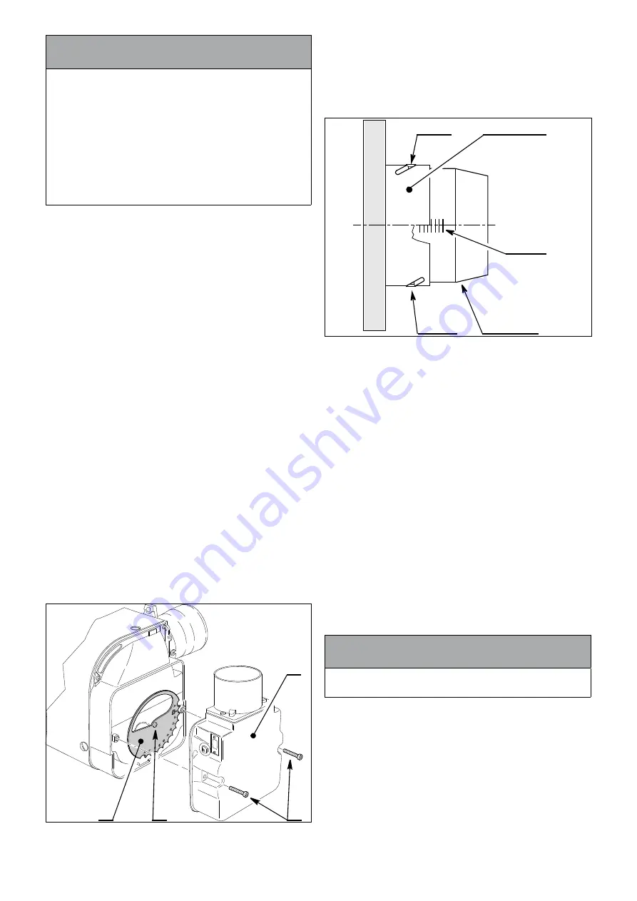
3. Undo the two screws (1) and remove the air inlet cover (B)
from the side of the burner.
4. The secondary air adjuster disc (A) is factory set in position
‘C’ - i.e. with the cut-out marked C located against the die-
cast boss on the fan housing - suitable for outputs of 18.5 kW
only. Refer to Figure 10-1.
5. Remove the screw (2) from the centre of the air adjuster
disc and reposition the disc such that the cut-out ‘B’
(corresponding to 15.5 kW output setting - refer to Section
2.2) is located against the cast boss on the fan housing.
6. Replace the screw in the centre of the air adjuster disc (A)
and tighten.
7.
Re-fit the air inlet cover (B) to the side of the burner and
reassemble in reverse order.
B
1
2
A
Figure 10-5:
Repositioning the air adjuster disc
10.3 COmBUStiON HEaD
aDjUStmENt - 58/70 ONLY
To adjust the combustion head when uprating to 70.0kW:
1. Loosen the two screws in the rings slots.
2. Turn the combustion head to setting 4.
3. Tighten the two screws.
Blast tube
Shutter
Screw
Slotted ring
0
Screw
Figure 10-6:
Adjusting the combustion head
10.4 SWitCHiNG ON
Switch on the electricity supply. The boiler will start as soon as the
electricity supply to the boiler is switched on.
BURNER
1. The burner fan should start and the burner should light within
about 12 seconds.
2. If the burner does not light and the ‘Lock-out’ reset button
lights, wait for about 45 seconds then press the reset button
to restart the ignition process. This procedure may have to be
repeated several times during first lighting.
3. With the burner alight, check the fuel pressure. Refer to the
Technical Information, Section 2.3.
4.
Adjust the pressure if necessary. Using a flat blade
screwdriver rotate the pressure adjustment screw on the
burner oil pump (see Figure 3-6) – clockwise to increase
pressure and anticlockwise to reduce pressure.
5. Operate the boiler until it reaches normal operating
temperature.
6. Check oil supply/return pipe for leaks, rectifying where
necessary.
! NOtE !
it is essential that the oil pressure is correctly set for clean
and efficient operation of the boiler.
BOiLER tHERmOStat
Check the operation of the boiler thermostat. Ensure that by
turning it anticlockwise it switches the burner off.
OiL SUppLY
1. With the burner alight, re-check the fuel pressure and
readjust if necessary.
2. Turn the boiler off, remove the pressure gauge and replace
the plug in the pump.
3. Ensure that there are no oil leaks, replace the burner cover.
Section 10: Commissioning
page 35
Summary of Contents for Vortex VTXBH1521
Page 51: ...Notes Page 51 NOTES...


