Disassemble and Clean the Pump (Daily)
Key
Key
Key
BA
Inlet Elbow with Camlock
BB
Inlet Housing Clamp
BC
Inlet Housing Assembly
BD
Inlet Ball
BE
Inlet Ball Stop
BF
Pump Rod Assembly
BG
Outlet Ball Stop
BH
Piston Seal
BI
Cylinder
BJ
Cylinder Clamp
BK
Outlet Housing
BL
Throat Packing
BM
Packing Nut (non-adjustable)
BN
Hopper
BP
Pump Outlet
BR
Hopper Release Camlock
BS
Outlet Ball
BT
Cylinder O-rings
BU
Outlet Housing Lock Nut
BV
Ball Cage Spring
Always
Always
Always Keep
Keep
Keep Spare
Spare
Spare Parts
Parts
Parts Stocked
Stocked
Stocked
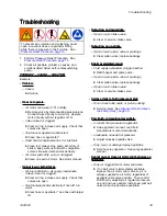
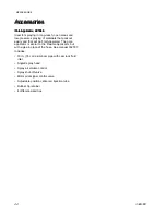
Always keep spare parts stocked to ensure getting
back up and running as quickly as possible. Parts
to keep stocked include:
• Cam and groove fitting gaskets
• Spray tips
• Tip retainer
• Rod and cylinder seals
• Cylinder o-rings
• Other parts as needed
To prevent skin injection and splashing, never
open a camlock hose or applicator fitting
while there is pressure in the fluid line. See
Pressure Relief Procedure, page 15
See the figure at the beginning of this section for part
references.
Disassemble and clean the pump at the end of every
day. The procedure takes about 10 minutes.
Note
NOTE:
NOTE:
NOTE: As items are disassembled, use a
soft brush and water or a compatible solvent
to clean components.
1.
Flush the system. See
. Stop
pump near bottom of its stroke.
2.
Perform Pressure Relief Procedure. See
Pressure Relief Procedure, page 15
3.
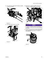
With fluid pressure relieved, remove material
hose from pump outlet (BP).
4.
Disconnect hopper at outlet camlock (BR) then
remove hopper (BN).
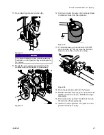
5.
Remove inlet elbow (BA).
6.
Tip cart back so it rests on the back of the cart.
Figure 38
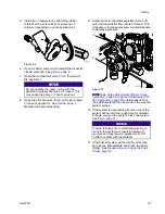
7.
While holding onto the inlet housing (BC), use
a 5/8 in. wrench to loosen the two nuts on
the inlet housing clamp (BB) then remove inlet
housing (BC).
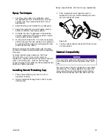
8.
Remove inlet ball stop (BE) and ball cage spring
(BV).
9.
Use 5/8 in. wrench (64) to loosen the two nuts on
the cylinder clamp (BJ) then remove cylinder (BI).
332612C
31

