background image

9

309711

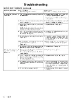
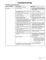
Troubleshooting

MOTOR IS HOT AND RUNS INTERMITTENTLY

TYPE OF PROBLEM

WHAT TO CHECK

If check is OK, go to next check

WHAT TO DO

When check is not OK refer to this column

Motor is hot and runs intermit-
tently.

1. Determine if sprayer was operated at high

pressure with small tips, which causes low
motor RPM and excessive heat build up.

1. Decrease pressure setting or increase tip

size.

2. Be sure ambient temperature where sprayer

is located is no more than 90

F and sprayer

is not located in direct sun.

2. Move sprayer to shaded, cooler area if pos-

sible.

ELECTRICAL SHORT

TYPE OF PROBLEM

WHAT TO CHECK

If check is OK, go to next check

WHAT TO DO

When check is not OK refer to this column

Building circuit breaker opens
as soon as sprayer switch is
turned on.

1. All electrical wiring for damaged insulation, and

all terminals for loose fit or damage. Also wires
between pressure control and motor. See page
18.

1. Repair or replace any damaged wiring or

terminals. Securely reconnect all wires.

2. For missing inspection plate gasket (see page

18), bent terminal forks or other metal to metal
contact points which could cause a short.

2. Correct faulty conditions.

3. Motor armature for shorts. Use an armature

tester (growler) or perform spin test. See page
10. Inspect windings for burns.

3. Replace motor. See page 18.

4. Motor control board (35) by performing motor

control board diagnostics on page 14. If diag-
nostics indicate, substitute with a good board. 

CAUTION:

 Do not perform this check until mo-

tor armature is determined to be good. A bad
motor armature can burn out a good board.

4. Replace with a new pressure control board

(35). See page 14.

1. Basic Electrical Problems on page 5.

1. Perform necessary procedures.

2. ON/OFF switch (23) See page 12. 

Be sure

sprayer is unplugged!

 Disconnect wires from

switch. Check switch with ohmmeter. Reading
must be infinity with ON/OFF switch OFF, and
zero with switch ON.

2. Replace ON/OFF switch. See page 12.

3. For damaged or pinched wires in pressure con-

trol. See page 14.

3. Replace damaged parts. See page 14.

Sprayer quits  after sprayer op-
erates for 5 to 10 minutes.

1. Basic Electrical Problems on page 5.

1. Perform necessary procedures.

2. Electrical supply with volt meter.

Meter must read 85–130 Vac.

2. If voltage is too high, do not operate

sprayer until corrected.

3. Tightness of pump packing nut. Over tightening

tightens packings on rod, restricts pump action,
and damages packings.

3. Loosen packing nut. Check for leaking

around throat. Replace pump packings, if
necessary. See page 19.

CAUTION

Any short in any part of the
motor power circuit will cause
the control circuit to inhibit
sprayer operation. Correctly
diagnose and repair all shorts
before checking and replac-
ing control board.

Building circuit breaker opens
as soon as sprayer is plugged
into outlet and sprayer is NOT
turned on.

Summary of Contents for SP

Page 1: ...on 3 Grounding 5 Troubleshooting 5 General Repair Information 4 Spin Test 10 Motor Brush Replacement 10 On Off Switch Replacement 12 Pressure Control Repair 14 Drive Housing Replacement 17 Motor Replacement 18 Displacement Pump Replacement 19 Technical Data 20 Graco Phone Number 20 GRACO INC P O BOX 1441 MINNEAPOLIS MN 55440 1441 COPYRIGHT 2003 GRACO INC Graco Inc is registered to I S EN ISO 9001 ...

Page 2: ...n un área donde la circulación de aire es deficiente y los vapores inflamables se pueden en cender al contacto con el fuego o chispas Para prevenir incendios y explosiones Use en espacios abiertos o en un área muy bien ventilada No utilice nunca tricloretano 1 1 1 cloruro de metileno u otros di solventes a base de hidrocarburos halógenos o fluidos que contengan tales disolventes en un equipo a pre...

Page 3: ...re Control Controls motor speed to maintain fluid outlet pressure at displacement pump outlet Works with pressure adjusting knob K ON OFF Switch Power switch that controls main power to sprayer M 50 ft 15 m Main Hose 1 4 in ID grounded nylon hose with spring guards on both ends N Spray Gun High pressure spray gun with gun safety latch P RAC IV Switch Tip Uses high pressure fluid to clear tip clogs...

Page 4: ...le connector Route wires carefully to avoid interference with other connections of pressure control Do not pinch wires between cover and control box 1 Keep all screws nuts washers gaskets and electrical fittings removed during repair proce dures These parts are not normally provided with replacement assemblies WARNING ELECTRIC SHOCK HAZARD MOVING PARTS HAZARD To reduce risk of serious injury inclu...

Page 5: ...ic Mechanical Problems 1 Pump 13 for frozen or hardened paint 1 Thaw sprayer if water or water based paint has frozen in sprayer Place sprayer in warm area to thaw Do not start sprayer until thawed completely If paint hardened dried in sprayer replace pump packings See page 19 Displacement Pump Replace ment 2 Displacement pump connecting rod pin 9a Pin must be completely pushed into connecting rod...

Page 6: ... Remove carbon with small cleaning brush Align brush leads with slot in brush holder to assure free vertical brush movement 10 Motor armature commutator for burn spots gouges and extreme roughness See page 10 10 Remove motor and have motor shop resur face commutator if possible See page 18 11 Motor armature for shorts using armature tester growler or perform spin test See page 10 11 Replace motor ...

Page 7: ...control circuit board 35 for damaged or loose wires or con nectors Inspect wiring insulation and terminals for signs of overheating 8 Be sure male terminal blades are centered and firmly connected to female terminals Replace any loose terminal or damaged wiring Securely reconnect terminals 9 For loose motor brush leads and terminals See page 10 9 Tighten terminal screws Replace brushes if leads ar...

Page 8: ...ould clog pump 5 Leaking around throat packing nut which may indicate worn or damaged packings See page 19 5 Replace packings page 19 Also check piston valve seat for hardened paint or nicks and replace if necessary Tighten packing nut wet cup 6 Pump rod damage 6 Repair pump page 19 7 Capacitor failure Visually inspect capacitor near terminals Ensure that orange safety re lief plug is intact 7 Rep...

Page 9: ...18 4 Motor control board 35 by performing motor control board diagnostics on page 14 If diag nostics indicate substitute with a good board CAUTION Do not perform this check until mo tor armature is determined to be good A bad motor armature can burn out a good board 4 Replace with a new pressure control board 35 See page 14 1 Basic Electrical Problems on page 5 1 Perform necessary procedures 2 ON ...

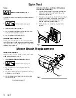
Page 10: ... and black motor leads together with test lead Turn motor fan by hand at about two revolutions per second 2 If uneven or no resistance check for broken brush springs brush leads motor leads loose brush terminal screws motor lead terminals worn brushes Repair as needed page 10 3 If still uneven or no resistance replace motor page 18 9578A Fig 3 F G 39 Motor Brush Replacement Motor Brush Removal Rep...

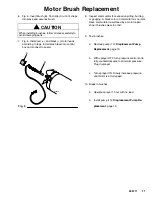
Page 11: ...Inspect commutator for excessive pitting burning or gouging A black color on commutator is normal Have commutator resurfaced by a motor repair shop if brushes wear too fast 9 Test brushes a Remove pump 13 Displacement Pump Replacement page 19 b With sprayer OFF turn pressure control knob fully counterclockwise to minimum pressure Plug in sprayer c Turn sprayer ON Slowly increase pressure until mot...

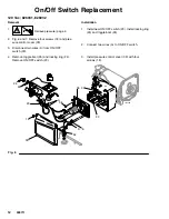
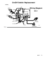
Page 12: ...ver 39 3 Disconnect two wires A from ON OFF switch 23 4 Remove toggle boot 25 and locking ring 24 Remove ON OFF switch 23 Installation 1 Install new ON OFF switch 23 Install locking ring 24 and toggle boot 25 2 Connect two wires A to ON OFF switch 3 Install pressure control cover 39 with four screws 18 ti3350a Fig 6 39 A 18 23 52 E D 35 36 25 24 37 22 ...

Page 13: ...f Switch Replacement 120 Vac Fig 7 Wiring Diagram 826031 A 826032 A Pressure Transducer ON OFF Switch Power Plug Potentiometer from Motor Capacitor Black Green White Yellow Black Red N L M M TO1 TO2 J7 J8 ti2159a TP1 ...

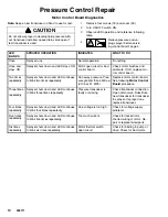
Page 14: ...continues to blink two times repeatedly Run away pressure Pres sure greater than 4500 psi 310 bar 31 MPa Replace motor control board See following Motor Control Board procedure Three times repeatedly Sprayer shuts down and LED continues to blink three times repeatedly Pressure transducer is faulty or missing Check transducer connection Open drain valve Substitute new transducer for transducer in s...

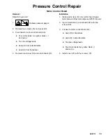
Page 15: ...ds Lead D from potentiometer Lead E from transducer 4 Remove five screws 36 and circuit board 35 Installation 1 Clean pad on rear of motor control board Apply small amount of thermal compound 073019 to pad 2 Fig 6 Install motor control board 35 with five screws 36 3 Connect to motor control board 35 Lead E to transducer Lead D to potentiometer Two line voltage leads Four motor leads two yellow bla...

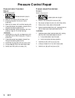
Page 16: ...r up through transducer grommet 28 3 Install filter housing 45 with two screws 22 4 Connect lead E to motor control board 35 5 Install cover 39 with four screws 18 Pressure Adjust Potentiometer Removal Refer to Fig 6 and 7 1 Relieve pressure page 4 2 Remove four screws 18 and cover 39 3 Disconnect all leads from motor control board 35 4 Remove five screws 36 and board 35 5 Remove potentiometer kno...

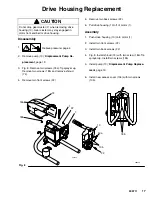
Page 17: ...sprayer up Remove two screws 18b and remove shroud 74 4 Remove two front screws 22 5 Remove two back screws 22 6 Pull drive housing 10 off of motor 1 Assembly 1 Push drive housing 10 onto motor 1 2 Install two front screws 22 3 Install two back screws 22 4 Fig 8 Install shroud 74 with two screw 18a Tip sprayer up Install two screws 18b 5 Install pump 13 Displacement Pump Replace ment page 19 6 Ins...

Page 18: ...crews 36 and board 6 Remove strain relief 37 Fig 6 and motor fan 2 7 Remove three screws 22 behind board and remove control housing 21 8 Remove four screws 22 and motor 1 from frame 63 Assembly 1 Install new motor 1 on frame 63 with four screws 22 2 Install control housing 21 with three screws 22 3 Install strain relief 37 Fig 6 and motor fan 2 4 Install board 35 with five screws 36 Connect all le...

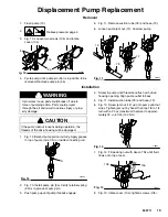
Page 19: ...uring operation the threads of the drive housing will be damaged 1 Fig 12 Extend pump piston rod fully Apply grease to top of pump rod at A or inside connecting rod Fig 12 A TI0062 2 Fig 10 Install pump pin 9a Verify retainer spring 9b is in groove of pump pin 3 Push pump up until pump threads engage 4 Screw in pump until threads are flush with drive housing opening Align pump outlet to back 5 Fig...

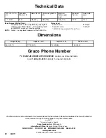
Page 20: ...744 measured at 3 1 feet 1 m Dimensions Weight lb kg Height in cm Length in cm Width in cm 34 5 15 7 17 75 45 1 14 5 36 8 13 5 34 3 Graco Phone Number TO PLACE AN ORDER OR FOR SERVICE contact your Graco distributor or call 1 800 690 2894 to identify the nearest distributor All written and visual data contained in this document reflect the latest product information available at the time of publica...

Reviews: