5-2
Spindl-Gard SG-1 and SG-2 Systems
L42110
5.2 SG-1 SPRAY NOZZLE
5.2.1
General:
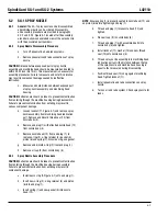
The SG-1 spray nozzle can be disassembled
and individual parts can be ordered. Disassembly
and assembly procedure are provided in paragraphs
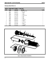
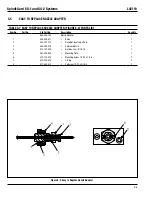
5.2.2 and 5.2.3. Figure 5-1 locat ed after the assembly
procedure, shows an exploded view of the spray nozzle
with the associated part numbers.
5.2.2
Spray Nozzle Disassembly Procedure
Turn off pneumatic air and lube systems.
a.
Remove pneumatic and lube connections at spray
b.
nozzle.
CAUTION:
Distance between exposed part of spray nozzle
assembly and machining head should be measured and noted to
within 0.032 inch (0.81 mm). This measurement is necessary for
assembly procedures. Failure to measure and note this distance
may result in component damage caused by ineffective
lubrication.
Measure and note distance between exposed part
c.
of spray nozzle assembly and machining head
hous ing.
CAUTION:
Extreme care should be taken to prevent contamination
from entering through the machine housing during disassembly.
Fail ure to prevent contamination from entering may result in
serious component damage.
Loosen locknut (11, Figure 5-1) and remove spray
d.
nozzle assembly from machining head lubrication
port. Remove and discard thread seal (10) from
nozzle body (8).
Remove end plug (1) with attached nozzle head (12)
e.
from nozzle body (8).
Remove nozzle head (12) from end plug (1), to
f.
remove o-ring (3), o-ring retainer (4), gasket (5),
pis ton (6) and spring (7). Discard o-ring and gasket.
Remove and discard o-ring (2) from end plug (1).
g.
Remove air cap (9) from nozzle body (8).
h.
5.2.3
Spray Nozzle Assembly Procedure
CAUTION:
Extreme care should be taken to prevent contamination
from entering through the machine housing during assembly.
Failure to prevent contamination from entering may result in
component damage.
Install new o-ring (2, Figure 5-1) onto end plug (1).
a.
Insert new o-ring (3), o-ring retainer (4) and piston
b.
(6) into end plug (1).
Insert spring (7) and new gasket (5) into nozzle
c.
head (12).
NOTE
: Ensure spring (7) is properly seated in nozzle head (12) and
on piston (6) before tightening end plug (1).
Thread end plug (1) into nozzle head (12) and
d.
tighten.
Place air cap (9) in nozzle body (8).
e.
Thread end plug (1) with assembled parts into
f.
nozzle body (8) and tighten.
Install locknut (11), washer (13) and new thread
g.
seal (10) onto nozzle body (8).
Thread spray nozzle assembly into machining head
h.
lubrication port until the distance between the top
of the spray nozzle and machine head housing is
equal to that measured during disassembly.
Position thread seal (10) snug against machining
i.
head. Tighten locknut (11).
Install pneumatic and lube connections on spray
j.
nozzle.
Turn on air and lube system. Check spray nozzle for
k.
leaks.
Summary of Contents for SG2
Page 1: ...Spindl Gard SG 1 SG 2 System Operation Service Instructions ...
Page 2: ......
Page 5: ...Spindl Gard SG 1 and SG 2 Systems 1 2 L42110 Figure 1 1 SG 1 System ...
Page 8: ...1 5 Spindl Gard SG 1 and SG 2 Systems L42110 1 6 Blank Figure 1 2 SG 2 System ...
Page 18: ...2 10 Spindl Gard SG 1 and SG 2 Systems L42110 Figure 2 10 Air Flow Switch and Mixing Tees ...
Page 19: ......
Page 26: ......
Page 36: ......


