2-5
Spindl-Gard SG-1 and SG-2 Systems
L42110
2.2.8
Electrical Requirements:
Electrical components such
as cycle switches, air flow switches, zero-leak valves,
etc., have 1/2 NPT ports for installation of the necessary
conduit fittings according to plant procedures. Refer to
schematics provided with the con troller to determine
proper wiring connections. Mount the controller in an
accessible location where connecting wiring does not
pose a hazard.
2.2.9
Pneumatic Connections:
When all required components
have been installed, pneu matic connections may be
completed. When installing pneu matic tubing, avoid
severe bends or kinks which could deter air flow. Keep
all air lines along the contour of the machining head.
2.2.10 Lube Line Connections
2.2.10.1
When all required components have been installed, lube
line connections may be completed. Connections are
required to connect the divider valves to the pump or
header and to connect the divider valves to the spray
nozzles or lube points.
2.2.10.2
Various inlet and outlet port types are available on MSP
divider valves. Matching port types are available on
nozzles and accessories. Steel or copper tubing with 3/8
inch (9.5 mm) OD is recommended from pump or header
to the divider valves. Steel or copper tubing of 3/16 or
1/4 inch (4.8 or 6.4 mm) OD is recommended from the
divider valves to the lubrication points or spray nozzles.
When installing tub ing, avoid sharp bends or kinks which
could deter lubricant flow. Keep all lube lines along the
contour of the machining head.
2.3
SG-2 SYSTEM INSTALLATION
2.3.1
General:
Paragraphs 2.3.2 through 2.3.8 discuss
the installation and mounting of components of SG-2
systems. Paragraphs 2.3.9 and 2.3.10 discuss the final
pneumatic and lube line connec tions which complete the
installation process. The informa tion provided in these
paragraphs is designed to apply to all applications. For
information on the specific system, refer to information
obtained from the design process.
2.3.2
Nozzle Tube Installation
2.3.2.1
Several different styles of nozzle tubes are available;
double-outlet, single-outlet and restrictor outlet. Figure
2-6 shows typical applications for each style. Typically,
one noz zle is required for each front or rear bearing
group. The ori fice(s) at the nozzle tip are directed toward
the rolling ele ment below the bearing cage assembly.
To avoid excess buildup of lubricant around the bearing,
drain holes need to be provided at the low point of each
bearing pocket.
2.3.2.2
Prior to installation of the nozzle tube (refer to para graph
2.3.2.3) the machining head requires modification as
follows:
CAUTION:
Before drilling into or disassembling machining head,
obtain prints to verify location of all drilling procedures. Thoroughly
remove all debris and chips after drilling to avoid possibility of
contamina tion.
NOTE
: The following procedure is for installation of nozzle tube
assemblies. If your applica tion uses the restrictor nozzle, complete
steps “a” and “b”, then tap the machining head to 1/8 NPT.
Disassemble machining head to the point necessary
a.
for bearing removal.
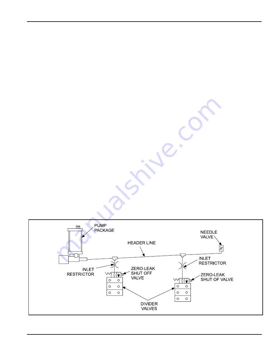
Figure 2-5. Pump and Header Installation
Summary of Contents for SG2
Page 1: ...Spindl Gard SG 1 SG 2 System Operation Service Instructions ...
Page 2: ......
Page 5: ...Spindl Gard SG 1 and SG 2 Systems 1 2 L42110 Figure 1 1 SG 1 System ...
Page 8: ...1 5 Spindl Gard SG 1 and SG 2 Systems L42110 1 6 Blank Figure 1 2 SG 2 System ...
Page 18: ...2 10 Spindl Gard SG 1 and SG 2 Systems L42110 Figure 2 10 Air Flow Switch and Mixing Tees ...
Page 19: ......
Page 26: ......
Page 36: ......


