2-7
Spindl-Gard SG-1 and SG-2 Systems
L42110
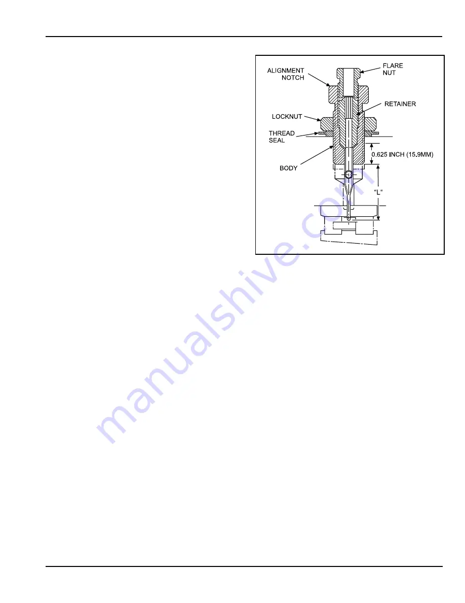
Thread body into machining head until nozzle tube
outlet(s) is/are at correct depth. Make sure notch on
body is directed toward bearing location.
Secure body in place with locknut.
f.
Install flare nut on body for safekeeping. Flare nut
g.
is used during lube line installation discussed in
paragraph 2.3.10.
2.3.3
Air/Oil Mixing Tee
2.3.3.1
One air/oil mixing tee is required for each nozzle used
in an SG-2 system. Each mixing tee is equipped with a
single 0.281 inch (7.14 mm) mounting hole. If more than
one mixing tee is used, tie rods are available to couple up
to four mixing tees together in a single manifold unit.
CAUTION:
If an air flow switch is used at a given application, only
three mixing tees may be coupled with tie rods. If more than three
mixing tees are provided air from a single air flow switch, the
pressure differential caused by a blocked or broken air line may
not be great enough to actuate the switch.
2.3.3.2
Figure 2-8 shows a sectional view of the mixing tee. For
installation, the lube inlet should always be positioned at
the top. This allows the oil to flow through oil tube (8) and
properly enter outlet fitting (9) where air is mixed with the
oil to create the laminar flow in the air/oil delivery tube.
Air and lube inlet ports are 1/8-27 NPSF. If mixing tees
are to be grouped together, remove plugs (7) from all but
the last tee. Roll pin (1) ensures that all tees are aligned
while o-ring (10) provides proper sealing for grouped
tees.
2.3.3.3
The air/oil delivery tube requires 0.125 inch (3.18 mm)
internal diameter and a minimum length of 2 feet (61 cm)
of tubing from the outlet fitting to the nozzle tube.
NOTE:
The outlet fitting used on mixing tees is specially
•
designed to provide proper air/oil flow through
the tube. Outlet fitting must not be replaced with
standard commercial fittings.
The air/oil delivery tube requires a 45 degree
•
inverted flare to seal properly in the nozzle tube
assembly.
Use only Graco-supplied nut on outlet fitting. Do not
•
use compression fittings.
Always install an external check valve at the lube
•
inlet of the mixing tee.
2.3.4
Divider Valve Installation:
Installation of divider valves
for SG-2 systems are similar to those used on SG-1
systems. Refer to paragraph 2.2.5 for SG-1 divider valve
installation.
2.3.5
Air Flow Switch Installation
2.3.5.1
The air flow switch monitors air flow to the mixing tees.
If an air line becomes plugged or broken, the decrease
or increase of air flow causes an increase or decrease of
air pressure. Pressure switches mounted in the air flow
switch enclosure detect the varied pressure and provide
a fault sig nal to the system controller.
2.3.5.2
One air flow switch can monitor up to three nozzle
assemblies. The switch should be positioned to keep the
dis tance between the air flow switches and the nozzle
assem blies to a minimum. Air flow switches are equipped
with two 0.281 inch (7.14 mm) mounting holes. Remove
the top cover to gain access to the mounting holes.
Figure 2-9 shows the air flow switch with cover removed.
The GAUGE port, locat ed on the side of the unit, may be
connected to a gauge to allow visual monitoring of the air
pressure or as an alternate air inlet. This port is factory-
shipped with an 1/8-27 NPT plug installed. Remove the
plug to install a gauge. If this port is used as an alternate
air inlet, plug the hole marked AIR INLET.
2.3.5.3
Installation procedures for the air flow switch are as
follows:
Remove top cover to gain access to the two
a.
mounting holes.
Position the air flow switch in a location protecting it
b.
from coolant spray.
Figure 2-7. Nozzle Tube Installation
Summary of Contents for SG2
Page 1: ...Spindl Gard SG 1 SG 2 System Operation Service Instructions ...
Page 2: ......
Page 5: ...Spindl Gard SG 1 and SG 2 Systems 1 2 L42110 Figure 1 1 SG 1 System ...
Page 8: ...1 5 Spindl Gard SG 1 and SG 2 Systems L42110 1 6 Blank Figure 1 2 SG 2 System ...
Page 18: ...2 10 Spindl Gard SG 1 and SG 2 Systems L42110 Figure 2 10 Air Flow Switch and Mixing Tees ...
Page 19: ......
Page 26: ......
Page 36: ......


