background image

3A8102A

EN

Application Methods

Parking Lot Layout for LineLazer

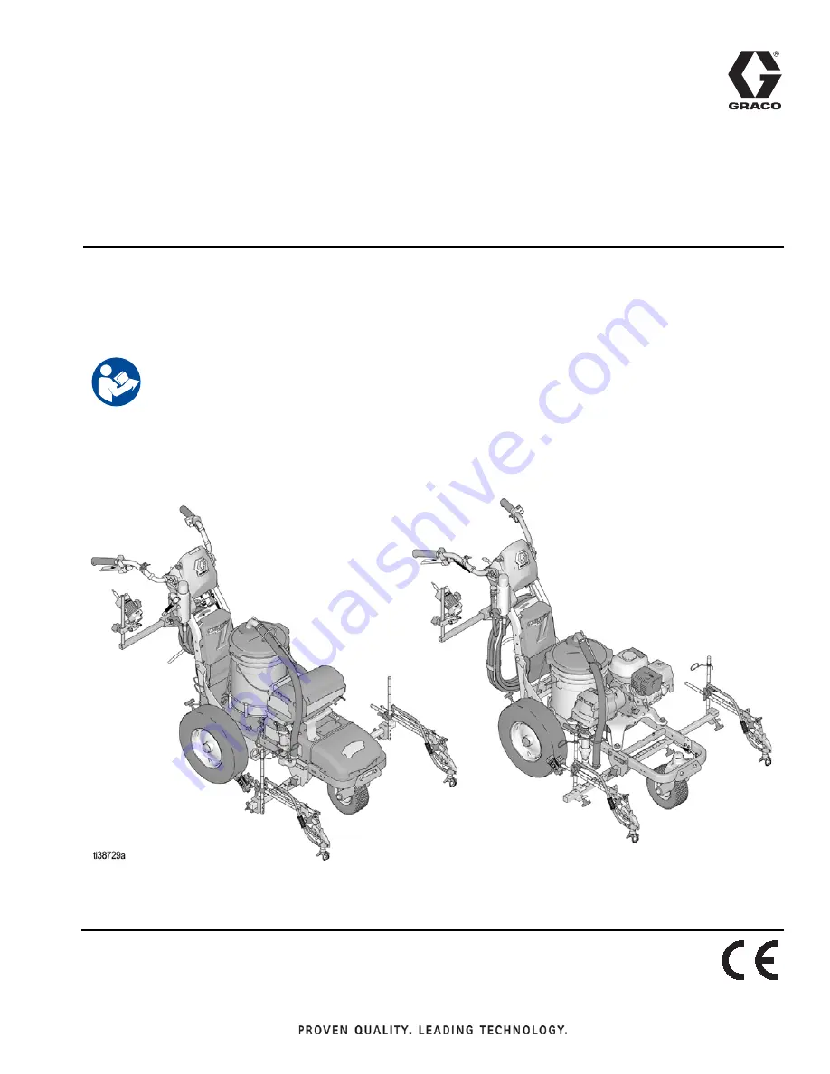
 V 

HP Auto Series with LazerGuide

 2000

For the application of line striping materials. For professional use only. For outdoor use 
only. Not for use in explosive atmospheres or hazardous locations.

Maximum Operating Pressure: 3300 psi (22.8 MPa, 228 bar)

Important Safety Instructions

Read all warnings and instructions in this manual and in related manuals.
Be familiar with the controls and the proper usage of the equipment. 
Save these instructions.

Summary of Contents for LineLazer V HP Auto Series

Page 1: ...r professional use only For outdoor use only Not for use in explosive atmospheres or hazardous locations Maximum Operating Pressure 3300 psi 22 8 MPa 228 bar Important Safety Instructions Read all warnings and instructions in this manual and in related manuals Be familiar with the controls and the proper usage of the equipment Save these instructions ...

Page 2: ...e 15 Radius Stall Layout Stall Calculator 16 Radius Stall Layout Layout Mode 17 Radius Stall Layout Stall Calculator 18 Radius Stall Layout Layout Mode 19 Radius Stall Layout Striping Mode 20 Angle Stall Layout Parking Mode 21 Angle Stall Layout Angle Calculation 22 Angle Stall Layout Layout Mode 23 Angle Stall Layout Striping Mode 24 Cross Hatch Layout Layout Mode 25 Cross Hatch Layout Striping M...

Page 3: ...traight across from one another slightly in front of the front tire STALL CALCULATOR OFFSET 1 Back the striper up to the curb or START reference dot near the curb then measure the distance from the curb or START reference dot to the LazerGuide 1700 Start Stop Laser under your spray gun 2 In the STALL CALCULATOR screen input this value as the offset x value by using Store this value by holding for ...

Page 4: ...TCH and move the LazerGuide 1700 Start Stop Laser along the tape measure and stop at the measurement 1 ft beyond the inputted measurement on the display to take into account that you started on the 1 ft mark NOTE The LiveLook display is measuring in both the forward and backwards direction so if you go past the FINISH point you can back up the striper before pressing the GUN TRIGGER CONTROL button...

Page 5: ...he striper in a straight line to the FINISH point and press the GUN TRIGGER CONTROL button when the LazerGuide 1700 Start Stop Laser is directly over the FINISH point At any time while in MEASURE MODE if an Auto gun is set to active momentarily hold down GUN TRIGGER CONTROL to apply a dot Holding down GUN TRIGGER CONTROL will produce continuous dotted line with 1 foot dot spacing when moving used ...

Page 6: ...the display so that the red LED is lit 3 Line the LazerGuide 1700 Start Stop Laser up with the inside curb Press the GUN TRIGGER CONTROL button to place your curb START reference dot and then move the striper away from the curb until the second START reference dot is placed 18 ft from the inside curb in this example 4 Press the GUN TRIGGER CONTROL button to stop placing additional reference dots 5...

Page 7: ... TRIGGER CONTROL button to start measuring Move the striper toward the FINISH reference dot while keeping the LazerGuide 2000 Laser lined up with the Target Box 3 Once you reach the FINISH reference dot press the GUN TRIGGER CONTROL button to stop measuring NOTE The LiveLook display is measuring in both the forward and backwards direction so if you go past the FINISH reference dot you can back up ...

Page 8: ...eference dot and align the LazerGuide 2000 Laser with the Target Box 2 Press the GUN TRIGGER CONTROL button to start laying dots at the defined width 9 03 ft in this example Move the striper toward the FINISH reference dot while keeping the LazerGuide 2000 Laser lined up with the Target Box 3 Press the GUN TRIGGER CONTROL button after the last FINISH reference dot is reached to stop laying additio...

Page 9: ...lowing the bottom curb until you make a second dot at 9 03 ft in this example 3 Press the GUN TRIGGER CONTROL button to stop laying additional dots 4 Rotate the striper 180 degrees such that the LazerGuide 1700 Start Stop Laser is directly over the reference dot that you just laid 5 Press the GUN TRIGGER CONTROL button to start laying dots at the defined width 9 03 ft in this example Move the stri...

Page 10: ...10 Application Methods Basic Stall Layout Striping Mode Paint lines connect the dots STRIPING MODE Connect the dots with your striper Use the Target Box if needed ...

Page 11: ...plan to lay out either using MEASURE MODE on the LiveLook display or a tape measure 2 Establish your stall START and FINISH reference dots by using the LAYOUT MODE and measuring from the CENTER reference dot in this example we are measuring 18 ft from the CENTER reference dots 3 Set the LazerGuide 2000 Target Box at one of the FINISH reference dots facing the corresponding START reference dot ...

Page 12: ...dth in this case we chose 9 ft and then press the GUN TRIGGER CONTROL button to start measuring Move the striper toward the FINISH reference dot while keeping the LazerGuide 2000 Laser lined up with the Target Box 3 Once you reach the FINISH reference dot press the GUN TRIGGER CONTROL button to stop measuring NOTE The LiveLook display is measuring in both the forward and backwards direction so if ...

Page 13: ...tart Stop Laser with the START reference dot and align the LazerGuide 2000 Laser with the Target Box 2 Press the GUN TRIGGER CONTROL button to start laying dots at the defined width 9 02 ft in this example Move the striper toward the FINISH reference dot while keeping the LazerGuide 2000 Laser lined up with the Target Box 3 Press the GUN TRIGGER CONTROL button after the last FINISH reference dot i...

Page 14: ...NOTE If doing multiple island stalls where the stalls are lined up you can save time by marking the first START ref erence dot and the final FINISH reference dot and use the skip line feature on the LiveLook display For example if you want 18 ft deep stalls and a 24 ft drive path you would select 36 ft line 24 ft skip ...

Page 15: ... inside curb 2 Set Gun 1 or 2 to active by pressing the 1 or 2 button on the display so that the red LED is lit 3 Line the LazerGuide 1700 Start Stop Laser up with the inside curb and press the GUN TRIGGER CONTROL button and then move the striper away from the curb until the outer radius reference dot is placed 18 ft from the inside curb in this example 4 Press the GUN TRIGGER CONTROL button to st...

Page 16: ...on to start measuring Move the striper toward the FINISH point while following the inner curb with the LazerGuide 1700 Start Stop Laser 3 Once you reach the FINISH point press the GUN TRIGGER CONTROL button to stop measuring NOTE The LiveLook display is measuring in both the forward and backwards direction so if you go past the FINISH reference dot you can back up the striper before pressing the G...

Page 17: ...ollowing the bottom curb until you make a second dot at 9 03 ft in this example 3 Press the GUN TRIGGER CONTROL button to stop laying additional dots 4 Rotate the striper 180 degrees such that the LazerGuide 1700 Start Stop Laser is directly over the reference dot that you just laid 5 Press the GUN TRIGGER CONTROL button to start laying dots at the defined width 9 03 ft in this example Move the st...

Page 18: ... the GUN TRIGGER CONTROL button to stop measuring NOTE The LiveLook display is measuring in both the forward and backwards direction so if you go past the FINISH reference dot you can back up the striper before pressing the GUN TRIGGER CONTROL button to subtract from the measurement 4 Use the UP DOWN arrows to adjust the number of stalls to match the number of stalls you selected when measuring th...

Page 19: ... up the LazerGuide 1700 Start Stop Laser with the START point 2 Press the GUN TRIGGER CONTROL button to start laying dots at the defined width 10 14 ft in this example Move the striper toward the FINISH reference dot while keeping the LazerGuide 1700 Start Stop Laser lined up with the perimeter reference line 3 Press the GUN TRIGGER CONTROL button after the last FINISH reference dot is reached to ...

Page 20: ...20 Application Methods Radius Stall Layout Striping Mode Paint Lines STRIPING MODE Connect the dots with your striper Use the Target Box if needed ...

Page 21: ...d on both ends of the island stalls that you plan to lay out either using MEASURE MODE on the LiveLook display or a tape measure 2 Establish your stall START and FINISH reference dots by using the LAYOUT MODE and measuring from the CENTER reference dot in this example we are measuring 18 ft from the CENTER reference dots 3 Set the LazerGuide 2000 Target Box at one of the FINISH reference dots faci...

Page 22: ... display and adjust the desired ANGLE STALL DEPTH and STALL SIZE NOTE The system will automatically calculate the offset and dot spacing 2 Press to transfer the dot spacing to LAYOUT MODE and press to transfer offset distance to LAYOUT MODE NOTE The system does not transfer any number from the ANGLE CALC to the LAYOUT MODE screen if is pressed ...

Page 23: ...de 2000 Laser with the Target Box 2 Press the GUN TRIGGER CONTROL button to start laying dots Move the striper toward the FINISH reference dot while keeping the LazerGuide 2000 Laser lined up with the Target Box 3 Press the GUN TRIGGER CONTROL button after the last FINISH reference dot is reached to stop laying additional dots 4 Move the Target Box to the second FINISH point and move the striper t...

Page 24: ...24 Application Methods Angle Stall Layout Striping Mode Paint Lines connect the dots STRIPING MODE Connect the dots with your striper Use the Target Box if needed ...

Page 25: ...esired spacing NOTE For best results always dot in the same direction NOTE Minimum engine RPM for placing dots is 2600 LAYOUT MODE 1 Set gun to active Press GUN TRIGGER CONTROL to START and FINISH dots 2 Adjust STALL SIZE to achieve desired cross hatch spacing 3 Place dots around perimeter of area ...

Page 26: ...ut Striping Mode Paint lines connect the dots STRIPING MODE Connect the dots with your striper Use the Target Box if needed NOTE Paint interior by connecting the dots If ends are rounded as shown make sure you establish this before painting ...

Page 27: ...Application Methods 27 Cross Hatch Layout Striping Mode Paint perimeter connect the dots STRIPING MODE Paint the perimeter ...

Page 28: ...RKER MODE Automatic marker layout example shows typical lane line layout for reflective markers Set space sizes up to 8 consecutive measurements By leaving zeros in any space AutoLayout will skip to the next measurement in a continuous loop OTHER USES Multiple spaced handicap stall layout Double line stalls ...

Page 29: ... defective parts The equipment will be returned to the original purchaser transportation prepaid If inspection of the equipment does not disclose any defect in material or workmanship repairs will be made at a reasonable charge which charges may include the costs of parts labor and transportation THIS WARRANTY IS EXCLUSIVE AND IS IN LIEU OF ANY OTHER WARRANTIES EXPRESS OR IMPLIED INCLUDING BUT NOT...

Page 30: ...lis International Offices Belgium China Japan Korea GRACO INC AND SUBSIDIARIES P O BOX 1441 MINNEAPOLIS MN 55440 1441 USA Copyright 2020 Graco Inc All Graco manufacturing locations are registered to ISO 9001 www graco com Revision A September 2020 Graco Information For the latest information about Graco products visit www graco com For patent information see www graco com patents TO PLACE AN ORDER...

Reviews: