


310314
11
Operation
Pressure Relief Procedure
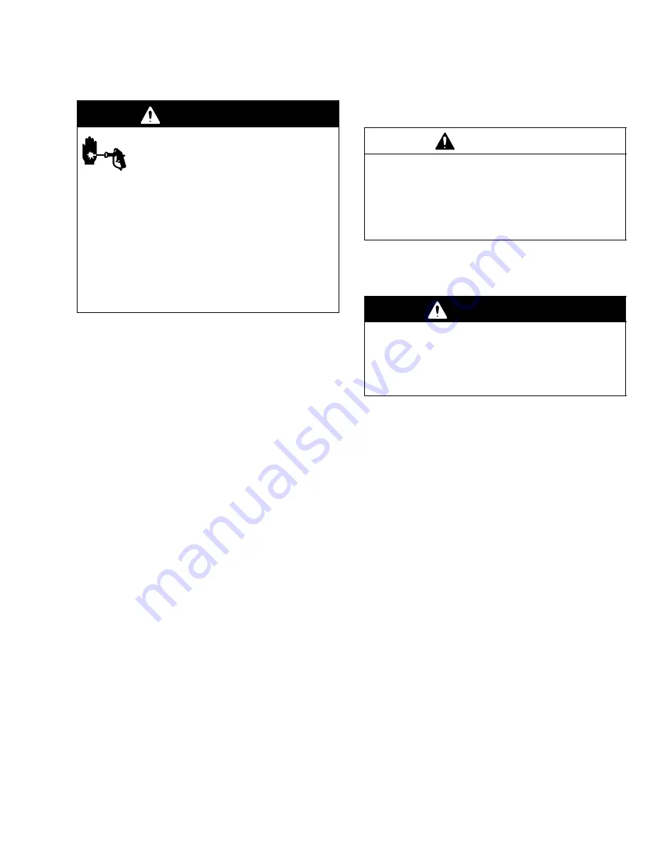
WARNING
INJECTION HAZARD
The system pressure must be manually
relieved to prevent the system from
starting or spraying accidentally. Fluid
under high pressure can be injected through the
skin and cause serious injury. To reduce the risk of
an injury from injection, splashing fluid, or moving
parts, follow the
Pressure Relief Procedure
whenever you:
D
are instructed to relieve the pressure,
D
stop dispensing,
D
check or service any of the system equipment,
D
or install or clean the dispense ball valve.
1.
Relieve system pressure to which Graco module
supply units are attached.
2.
Close dispenser ball valves (S). Unhook ball valves
from system. See Fig. 1.
3.
Close pump air bleed valve (H, required in your
system). See Fig. 1 or Fig. 5.
4.
Shut off main air bleed valve (E, required in your
system). Set ram director valve (U) to DOWN.
Ram will slowly drop.
5.
Hold metal part of dispenser ball valve firmly to
side of grounded metal pail, and open ball valve to
relieve pressure.
6.
Close dispenser ball valve.
7.
Repeat procedure for each ram (for models
970056, 970071 and 970073 only).
Flushing the System
Flush the system before initial use to prevent material
contamination.
CAUTION
Flush the system before performing the initial
material loading procedure.
The system was fac-
tory-tested using a light soluble oil, a soybean oil, or
other oil as tagged. Flush the system to avoid con-
taminating the material that has been designated for
initial material loading.
To flush the system, perform the following procedure:
1.
Select material to be used.
WARNING
Use fluids and solvents that are chemically compat-
ible with the equipment wetted parts. Refer to the
Technical Data
sections of all the equipment
manuals. Always read the material manufacturer’s
literature before using fluid or solvent in this pump.
2.
Verify that factory-test oil and material are compat-
ible:
a.
If substances are compatible, omit following
step b and
proceed to step 4.
b.
If substances are incompatible, perform re-
maining steps to flush system.
3.
Select drum of solvent that dissolves, cleans, and
eliminates factory-test oil from system. If neces-
sary, check with Graco Distributor or material sup-
plier for recommended solvent.
4.
Before flushing, be sure entire system and flushing
drums are properly grounded. Refer to
System
Grounding
, on page 8.
5.
Using compatible solvent, perform
Starting and
Adjusting System Rams
procedure and
Starting
and Adjusting the Pump
procedure on page 13.
6.
Flush solvent through system for 1 to 2 minutes.
7.
Remove drum containing solvent.


