


3A7467D
EN
Instructions
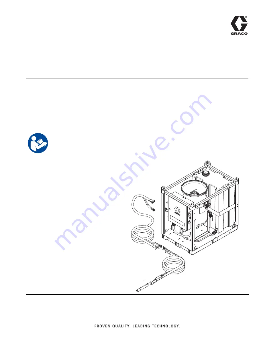
EcoQuip 2
™
EQs, EQc, and EQ Trailer Unit
Vapor Abrasive Blast System
Vapor abrasive blast system for coating removal and surface preparation.
For professional use only.
175 psi (12.06 bar, 1.2 MPa) Maximum Working Pressure
See page 4 for models and approval information.
Important Safety Instructions
Read all warnings and instructions in this
manual before using this equipment.
Save these instructions.
WLD
WLLD
Summary of Contents for 262960
Page 10: ...Component Identification 10 3A7467D Component Identification WL D WLL D 3 1 4 5 6 7 8 9 0 ...
Page 44: ...Parts 44 3A7467D EQ200T Parts WL F 1 Apply thread sealant to all non swivel pipe threads ...
Page 46: ...Parts 46 3A7467D EQ400T Parts 1 Apply thread sealant to all non swivel pipe threads ...


