background image

Operation

334852D

5

Setup Mode

1.

Press the TOTAL and RESET buttons (F

IG

. 5) 

together. 

All segments of the digital display 
illuminate for approximately 4 seconds.

The software revision displays for approximately 
1 second.

The meter goes blank and the volume unit 
blinks. 

The meter is now in Setup Mode.

2.

Release the TOTAL and RESET buttons.

Volume Unit 

3.

The default Unit of Measure (UOM) is Quarts (QTS). 

Repeatedly press the TOTAL button (F

IG

. 2) to 

change the displayed UOM. F

IG

. 4 shows examples 

of each UOM screen.

4.

When the desired UOM is displayed, press the 
RESET button (F

IG

. 2) to save the selection. 

5.

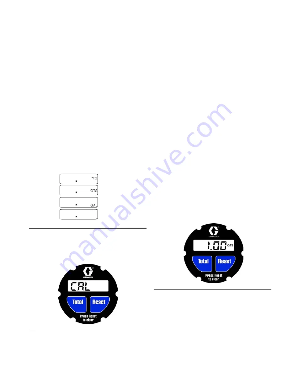
CAL appears on the display as shown in F

IG

. 5. CAL 

indicates the meter is ready for Calibration Mode.

6.

If you do not want to Calibrate the meter, to exit 
Setup, press the RESET button again. To Calibrate 

the meter, see Calibration Mode instructions in the 
following section of this manual.

Calibration Mode

The meter has a preset calibration factor from the 
factory. 

From the CAL screen:

NOTE:

 Instructions for displaying the CAL screen are 

provided in Setup Mode, steps 1 - 5.

1.

To save the current Calibration factor, press RESET 
and the unit will save and exit setup.

2.

To recalibrate the meter:

a.

Dispense 1 Quart (or 1 Liter) of fluid into a 

clean, calibrated container. 

b.

When the volume of fluid in the calibrated con-

tainer reaches 1 Quart (or 1 Liter), stop the dis-

pense.

NOTE:

 During the dispense the numbers on the 

display and the UOM flash on the screen. 

c.

Press and hold the TOTAL button until 1.00 QTS 

(or 1.00 L) displays steady on the screen. F

IG

. 6 

shows the meter displaying 1.00 QTS has been 

dispensed.

d.

If you are satisfied with the dispense, press the 

RESET button to save the new calibration factor 

and exit the Setup Mode.

e.

If the dispense was not accurate and needs to 

be performed again, repeat Step 2, a - d

F

IG

. 4: Example of Units of Measure (UOM)

F

IG

. 5

F

IG

. 6

Summary of Contents for 24V553

Page 1: ...heres or hazardous locations For professional use only Models 24V553 Measures in gallons quarts pints and liters Meter is factory set in quarts Calibrate after electronic module replacement 1500 psi 10 3 MPa 103 bar Maximum Working Pressure Important Safety Instructions Read all warnings and instructions in this manual Save these instructions ...

Page 2: ...ace worn or damaged parts immediately with genuine manufac turer s replacement parts only Do not alter or modify equipment Alterations or modifications may void agency approvals and create safety hazards Make sure all equipment is rated and approved for the environment in which you are using it Use equipment only for its intended purpose Call your distributor for information Route hoses and cables...

Page 3: ...d installing an in line meter It is not an actual system design Contact your Graco representative for assistance in designing a system to suit your needs Key A In line meter B In line strainer C Shutoff valve D Pressure relief valve E Check valve F Bleed off valve drain valve G Bleed type master air valve FIG 1 A B C D E F G ...

Page 4: ...y running fluid through the meter FIG 2 NOTE The digital display on the meter goes blank after approximately two minutes of non use Function of TOTAL To see the accumulated total of fluid dispensed through the meter press the TOTAL key The meter can accu mulate a running total of up to 19 999 units dispensed before returning to zero FIG 3 Function of RESET Press the RESET key to clear the quantity...

Page 5: ... instructions in the following section of this manual Calibration Mode The meter has a preset calibration factor from the factory From the CAL screen NOTE Instructions for displaying the CAL screen are provided in Setup Mode steps 1 5 1 To save the current Calibration factor press RESET and the unit will save and exit setup 2 To recalibrate the meter a Dispense 1 Quart or 1 Liter of fluid into a c...

Page 6: ...the lowest possible set ting for dispensing fluid 3 Put the tip of the nozzle at the bottom of the cali brated container 4 If the tip of the dispense valve does not reach the bottom of the calibrated container use a length of plastic tubing over the tip of the nozzle to ensure liq uid enters the container from the bottom 5 Trigger the gun slowly so the fluid immediately cov ers the tip of the disp...

Page 7: ... Cause Solution Digital display is dim Battery in electronic control is worn out Replace battery See page 8 Electronic control is malfunctioning Replace the electronic control Order Part No 24V554 Digital display does not activate Battery in electronic control is worn out Replace battery See page 8 Electronic control is malfunctioning Replace the electronic control Order Part No 24V554 There is no...

Page 8: ...screwdriver or similar tool between the battery and the positive terminal bat tery retainer in the electronic control to remove the battery as shown in FIG 8 5 Insert the new battery with the negative side of the battery position to the bottom of the battery holder Press the battery firmly down until the positive ter minal clips above the battery See FIG 9 Battery Side View to identify the negativ...

Page 9: ...he cover off Remove and discard the screws 6 Lift off the electronic control 3 Remove and discard the large o ring 4 screws and electronic control according to all standards for disposal 4 Install the new large o ring 4 over the lip on the top of the metering unit 2 Align the notch on the side of the new electronic control module 3 with the notch on the side of the metering unit 2 5 Install new sc...

Page 10: ...cluded in Kit 24V554 This kit also includes a disposable grounding strap not shown Underside view 1 6 3 4 2 7 Ref Part Description Qty 1 191782 GUARD impact 1 2 METERING UNIT gal lon quart pint liter 1 3 24V554 KIT electronic control 1 4 109137 O RING 1 6 112093 SCREW 6 7 BATTERY ...

Page 11: ...ressure Loss Tested in 10W oil at 70 F 21 C Flow rate varies with fluid pres sure temperature viscosity 150 psi 12 gpm 1 03 MPa 10 3 bar 45 4 lpm Weight 1 9 lb 0 95 kg Units of measurement Factory set in quarts Display shows quantity in 0 01 incre ments up to 199 99 gallons quarts pints or liters Total dis plays up to 19 999 units Inlet and outlet 1 2 npt non directional flow Operating temperature...

Page 12: ...not disclose any defect in material or workmanship repairs will be made at a reasonable charge which charges may include the costs of parts labor and transportation Disclaimers and Limitations The terms of this warranty constitute purchaser s sole and exclusive remedy and are in lieu of any other warranties express or implied including warranty of merchantability or warranty of fitness for a parti...

Reviews: