Appendix G - Communications Gateway Module Installation Kit
104
3A2797ZAA
I/O Signal Descriptions
This section provides details about the CGM
Automation Input and Output Signals.
PLC/Robot (CGM) Control Request (O33):
This bit must be set (high) before the HFR or NVH will
honor any output request from the PLC, robot or
controlling logic. Furthermore, the controlling logic
needs to provide a dynamic signal to O34 (heart beat
from PLC (#)) before requesting control of the HFR or
NVH system (refer to “#” note). A simple logic rung
where the heart beat output from the HFR (I168) is
provided to O34 will satisfy this condition. If the
controlling logic only wants to monitor HFR/ NVH
activity, clear or make O33 low.
Mode Selection (Input Instance 7, Output
Instance 0)
The signals shown in the following table represent the
mode of the HFR or NVH system. The modes shown in
the following table are available:
Shot Number (Input Instance 8, Output
Instance 1):
Shot recipes are typically defined on the ADM shot
setup screen pages. A shot consists of a dispense rate
(flow or pressure) and an amount dispensed (volume,
weight or time). The rate is determined if the machine is
in constant flow or constant pressure modes. The
amount is determined if in volumetric, weight, or a time
based amount mode.
Sequence and Sequence Positions (Input
Instances 8 and 9, Output Instances 1 and
2):
When in sequence mode, the data element represents
the current (input) or selected (output) position of
sequence of shot recipes. The HFR/ NVH system
provides capability for 26 different sequences (A – Z),
each with up to 20 positions. The sequences can be
defined using the sequences screens in the ADM. See
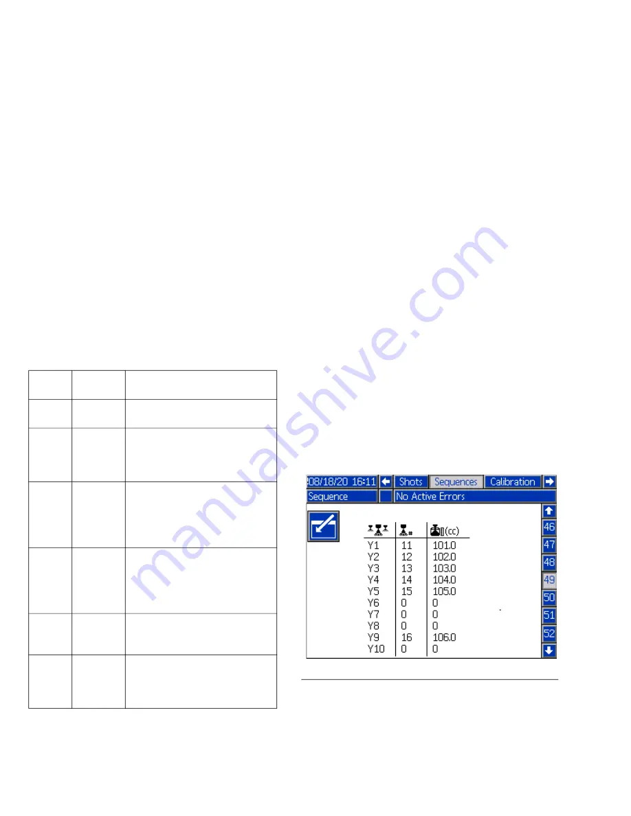
. 44. Positions in possible 20 positions can be
skipped, and the HFR/ NVH will automatically execute
the next defined position. For example, if the controlling
PLC requests Sequence Y (#25) position 1, as illustrated
in F
. 44 below, the HFR will execute shot 11 from
position 1, shot 12 from position 2, shot 15 from position
5, and finish the sequence with shot 16 from position 9
after each dispense request (O29). To execute the entire
sequence, the controlling PLC needs to generated6
dispense requests when the dispense is to occur. If the
controlling PLC requests a position or sequence which
is not defined (for instance, sequence Y position 7), the
un-defined portion of the request will be ignored.
System Startup Control (I171,O26)
Setting the O26 bit will request the following items,
based on the figuration of the HFR or NVH system:
Mode
Number
Mode
Name Description
1
Disabled Mode when system is OFF.
System is off and dormant.
2
Standby
Mode for Parking the pumps,
starting circulation (NVH), open
-
ing the Dispense Valve. Can
NOT dispense in this mode
3
Shot
Mode for dispensing set amount
of material. Up 100 shot recipes
(recipe is a dispense rate ((flow
or pressure)) and amount) are
available.
4
Sequence
Mode for dispensing a
sequence of up to 20 shot reci
-
pes. Up to 26 sequences can
be used and stored by the HFR/
NVH.
5
Operator
Mode for dispensing at a given
rate, with no pre-calculated
amount.
7
Night
Mode for recirculating and con
-
ditioning the materials, while
machine not in use. Can NOT
dispense material in this mode.
F
IG
. 44 Typical Sequence Definition Screen.
Summary of Contents for 24N572
Page 31: ...Setup 3A2797ZAA 31...


