7
safety, they have had the benefit of supervision or of instructions on the use of
the appliance. Children must be supervised to ensure that they do not play with
the appliance.
The water and electrical connections must be made by qualified technicians
(authorised plumber/electrician) in compliance with the installation regulations
in force.
Use the pump only within the limits specified on the rating plate (fig. 13 ref. A)
Do not run the pump with the flow port closed or dry.
Provide adequate ventilation for motor cooling purposes.
Protect the pump from the weather, avoiding ice formation.
Make sure that the rated voltage and the mains voltage are compatible (fig. 13
ref. B)
As additional protection from lethal electrical shock, install a high-sensitivity
differential switch (30 mA).
Disconnect the power supply to the electric pump before carrying out any
maintenance, cleaning or handling operations.
On models supplied with a cable and plug, if the power cable is damaged it
must be replaced by the manufacturer or by their technical assistance service,
or anyway by a person with similar qualifications, so as to prevent any risk.
During operation, the outer surface of the pump (if hot liquids are being
pumped) and the outer surface of the motor can exceed 40°C. Do not touch
with parts of your body (e.g.: hands) and do not put combustible material into
contact with the pump.
4
Installation (fig. 2 and 3)
When you receive the pump, check the outside of the package for evident signs of damage. If the product bears
visible signs of damage, notify our distributor within 8 days from the delivery date.
This pump is classified as an appliance for fixed installation, permanently connected to the electric mains (EN 60335-
1). Screw the electric pump to a stable base using the slots in the foot. In case of connection to the water system, the
regulations issued by the competent authorities (municipal, public utility company...) must be observed. Authorities
often require the installation of a backflow prevention device, such as a disconnector or check valve or disconnection
tank.
Proper installation (fig. 2)
Improper installation (fig. 3)
A= eccentric adapters
B= positive lift
C = wide bends
D = suction pipe diameter >= pump port diameter
E= good immersion
F= foot valve (not necessary for GBG models)
G = suction lift (*)
H= pipes must not exert stress on pump but on
independent supports
1 = tight bend
2 = negative lift
3 = pipe diameter < pump port diameter
4 = insufficient immersion
5 = lack of supports
(*) The suction lift depends on the type of pump (NPSH required by the pump) and on the installation (altitude, flow
resistance, liquid temperature). See table 10.
5
Electrical connection (fig. 4, 5 and 6)
To connect, proceed as shown on the back of the terminal board cover (anticlockwise rotation) and in fig. 4 for single-
phase versions, fig. 5 for three-phase versions. Use standard 3-wire cables (2+ground) for single-phase versions, 4-
wire cables (3+ground) for three-phase versions. The reference characteristics (voltage, frequency and input current)
are shown on the pump rating plate.
The single-phase pumps have built-in, automatic reset thermoamperometric protection.
On three-phase pumps, install a protection device with the following characteristics:
voltage 380-415V, input current 10 A.
In accordance with installation regulations, a device must be provided in the fixed
supply system which ensures disconnection from the mains, with a contact opening
distance that allows complete disconnections in current overload conditions category III.
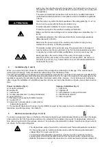
ATTENTION


