background image

Conveyor belts 


Page 41 

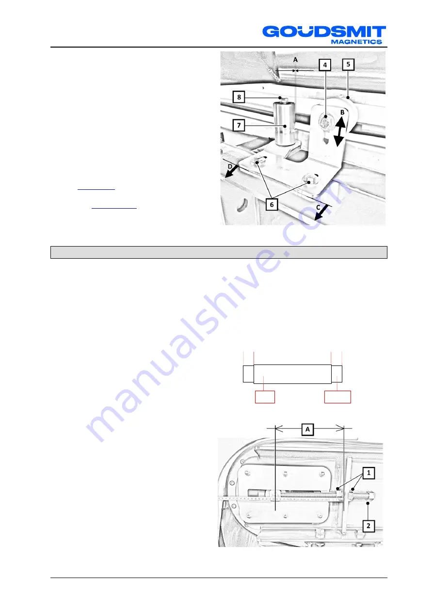
8.  Place the belt guide rollers on the frame. 
9.  Install the bolts (6) hand-tight. 
10.  Align the wheel of the guide roller (5) so 

the guiding snare of the belt falls in the 

wheel. 

11.  Make sure distances C and D are equal 

and tighten the bolts (6). 

12.  Loosen bolt (4), move the wheel so it is 

just above the profile and tighten the bolt. 

13.  Loosen bolt (8), move the roller (7) so 

distance A (free space between the belt 

and the roller) is 3 mm and tighten the 

bolt. 

14.  Check/correct the tension of the belt, see 

belt tension

 on page 43. 

15.  Check/adjust the alignment of the belt, 

see 

belt alignment

 on page 44. 


Adjusting belt alignment 

Warning! 

It is very important that the belt runs 

completely free. 

To prevent fast wear (and early 

replacement of the belt) make sure the 

belt is not touched by the (covers of the) 

machine. 


1.  Measure the distance from the side of the 

belt to the end of the roller on the left-

hand side (D) and on the right-hand side 

(E). 

They must be approximately the same. 

           D                                E 


2.  When the distances are not the same, 

adjust them as follows. 


3.  When the belt needs to move to the left-

hand side, the length of the left-hand 

adjustment possibility needs to decrease 

so distance (A) will decrease. 

In this way the belt is “pushed” towards 

the left-hand side. 


Note: the more distance (A) is decreased, 

the faster the belt will move towards that 

side.


4.  Loosen locknuts (1), count the number of 

turns and rotate the adjustment (2) so 

length A decreases. 


Belt 

Roller 

Summary of Contents for RNF Series

Page 1: ...uited for sticky or wet fluid products and or surroundings The descriptions and pictures in this manual used for explanation may differ from your machine We have enclosed the as built drawing of the d...

Page 2: ...nual is protected by copyright It is prohibited to copy any content images or other components it contains This manual may not be duplicated in any manner whatsoever and may not be transmitted and or...

Page 3: ...ease for SNL bearing blocks of the magnet roller Chapters Maintenance Bearing systems and Maintenance Motor reductor changed 2 0 10 2009 Specifications sheet and declaration by the manufacturer separa...

Page 4: ...l together with any relevant drawings and technical descriptions we supply remain our property It may not be duplicated or disclosed without our prior written permission The user manual can be ordered...

Page 5: ...current separation 18 Sigmatek touchscreen control 19 Emergency stop 21 Construction NF separator 22 Non ferro NF separator 23 Installation 24 Construction parts 24 Placing transporting or moving the...

Page 6: ...and or model of our products at any time whatsoever without any obligation to modify any previously supplied products accordingly Ferromagnetism The working principle of the device is based on Ferro m...

Page 7: ...original parts or non 100 exchangeable parts are used Lubrication products other than those prescribed are used The equipment is used injudiciously incorrectly negligently or not in accordance with it...

Page 8: ...e delivery deliveries the absence of anything additionally ordered Contact GOUDSMIT Magnetic Systems B V in the event of any damage and or mistaken delivery Identification plate On the device an ident...

Page 9: ...re necessary Make sure every person who comes in contact with the device wears adequate personal protection overalls safety glasses hearing protectors helmet steel toed safety shoes etc Areas of the d...

Page 10: ...c tools and workbenches fitted with a wooden worktop and preferably a non Fe frame for instance stainless steel Always be aware that Ferromagnetic parts will be attracted even personal items if you ar...

Page 11: ...rts pointing out There must never be long parts in the product flow because this magnetic device is only suited for small parts and particles Falling parts The moving product towards on and or leaving...

Page 12: ...not restore power until the dangerous situation has been resolved Lock Out Tag Out LOTO Lock Out Tag Out LOTO is an internationally agreed safety procedure to make sure that dangerous machines are pro...

Page 13: ...ibed because the magnet will lose magnetic force permanent when exposed to higher temperatures Free space Make sure that there is sufficient free space around the device to perform and ease the cleani...

Page 14: ...ferromagnetic materials from the product flow If included regularly check for wear on the drum exterior and the separation flap In a NF separator ferromagnetic materials must be removed before High p...

Page 15: ...ed Fe objects will fall off the drum into the Fe outlet To ensure that the Fe objects are pushed out of the powerful magnetic field several carriers ribs are welded to the casing Raw product contamina...

Page 16: ...he correct position This can be done as follows 1 Loosen the clamp bush bolts The magnet is mounted on the shaft that is now loosened Rotate the magnet segment to the desired position by rotating the...

Page 17: ...re ejected by the alternating magnetic field Drawing Eddy current principle The non electro conductive materials fall down straight after they have passed the magnet roller The separated non ferro par...

Page 18: ...n magnetiseable metals Aluminium 37 0 2 700 13 7 Magnesium 21 7 1 740 12 5 Copper 59 9 8 960 6 7 Silver 62 1 10 500 5 9 Zinc 16 9 7 140 2 4 Gold 41 7 19 320 2 2 Brass 15 2 8 500 1 8 Cadmium 13 3 8 650...

Page 19: ...fferent to the configuration shown here The vertical column on the left hand side shows the instructions and the bottom horizontal row generally shows control buttons Click on the icon if you want an...

Page 20: ...ral control one needs to press the remote button However you need at least login level 1 to do this To login to level 1 enter code 3283 and press the enter button Then press the remote button You are...

Page 21: ...stop On both sides of the NF separator emergency stops are mounted After the emergency stop is pressed the vibratory motors switch off and the magnet roller drive and belt drive will decelerate and t...

Page 22: ...or with an adjustable speed Magnet roller rotating frequency is approximately 3000 rpm The Magnet roller can be provided with a ceramic coating for more wear resistance It also has a tension unit to a...

Page 23: ...points for easer belt exchange For belt guiding guide rollers are placed along the belt To prevent dirt entering the device housing side profiles are placed on the belt and also 2 rubber dirt flaps ar...

Page 24: ...lled without risk Use only lifting hoisting and transport equipment that is in good condition and never exceed the safe working load of the equipment being used The weight of the device is stated on t...

Page 25: ...ees with rotation possible towards the separation plate Procedure Always perform the work with two technicians one on the drive side and the other on the non drive side Unscrew the nut of the lock bol...

Page 26: ...e electrical power supply is switched off while you work on the device Make sure that all electrical connections are made by qualified personnel and conform to all the applicable standards Check that...

Page 27: ...ing wear In the chapter MAINTENANCE we describe how the belt alignment and the belt tension must be and how to change them if necessary Mechanically setting the vibratory motor s If the vibratory moto...

Page 28: ...ng the production channel The device is thoroughly cleaned internally and externally The product does not fall into the magnet device from a greater height than 10 meters That the entire installation...

Page 29: ...the control unit will add an extra greasing instruction Regularly check if the bearings make more noise than usual or if they are warmer than normal If this is the case find out what the cause is and...

Page 30: ...may be pushed out of their seats If possible grease when running Greasing the smaller bearings higher nipple position Grease the nipples once every two weeks or every 200 hours about 0 5 1 0 cm 3 abo...

Page 31: ...grease recommendation Replace oil seal do not install it in the same track Depending on the operating conditions see chart below every 5 years at the latest According to oil temperature Change synthe...

Page 32: ...sure that the conveyor belt and rollers are cleaned regularly Contamination can cause extra wear to the belt and or misalignment of the belt As an extra cleaning measure the NF separator can have an...

Page 33: ...eeder conveyor belt 2 Remove the cover 3 and remove the bolt behind it 3 Remove the bolt 1 4 Remove the motor 2 from the drive roller 5 Remove the attachment bolts 4 of the scraper 6 Remove the scrape...

Page 34: ...n the attachment bolts on the other side but do not remove them 15 Use the hoist crane to lift the upper frame away from the supports until the gap is approximately 10 cm 16 Ask for assistance of a se...

Page 35: ...om its supports 5 Ask for assistance of multiple colleagues and place the new belt on the rollers 6 Place the new belt in the middle of the rollers so distances x are equal 7 Make sure the belt is not...

Page 36: ...ive roller and install both attachment bolts 6 13 Place the cover 7 14 Check correct the tension of the belt see the chapter Checking belt tension on page 43 15 Check adjust the alignment of the belt...

Page 37: ...urrent conveyor belt 1 Switch off the main switch and perform Lock Out Tag Out see LOTO on page 12 2 Rotate both locks 1 a quarter of a turn to unlock them 3 Remove the cover 2 4 Repeat step 2 and 3 f...

Page 38: ...e tensioners 5 on both sides to the lowest setting arrow 8 Attach a hoist crane with lifting strap through the cover frame 6 9 Remove all bolts 3 10 Remove the attachment bolts 1 of the emergency butt...

Page 39: ...e with a lifting strap to the beam Note to be able to place the new conveyor belt the main supports of the inner frame have been split up in a fixed large piece and a removable short piece 16 Remove a...

Page 40: ...otation 2 Ask for assistance of colleagues and place the new belt in the centre on the rollers so distances x are equal belt x x roller 2 Place the upper and lower frame support brackets 3 Lower the u...

Page 41: ...alignment Warning It is very important that the belt runs completely free To prevent fast wear and early replacement of the belt make sure the belt is not touched by the covers of the machine 1 Measur...

Page 42: ...it must be The recommended belt tension depends on operational circumstances In a light duty installation the belt will be tensioned no more than 0 5 1 0 If the tension of the belt is too high or too...

Page 43: ...has to be stopped immediately and adjusted using the driving roller and or reversing roller Correct alignment Incorrect alignment Measure the distances from the side of the belt to the end of the roll...

Page 44: ...g direction of motor Alter motor direction Separation plate set incorrectly Reset separation plate Poor separation of small particles even after optimisation Too few magnet poles even with highest rot...

Page 45: ...to this user manual in the added data sheet The spare parts are mostly wear parts such as bearings motor s cogs wheels conveyor belt protective coating on vibratory feeder and spring under vibratory f...

Page 46: ...sed company and always observe the local regulations in regard to disposal of industrial waste Storage If the device will not be used for a long period of time we advise to store the device in a dry s...

Reviews: