Operating Instructions
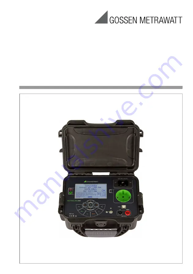
METRALINE PAT
Test Instrument for DIN VDE 0701-0702
3-447-022-03
2/4.19
Page 1: ...Operating Instructions METRALINE PAT Test Instrument for DIN VDE 0701 0702 3 447 022 03 2 4 19 ...
Page 2: ...ing Protection Class I Devices to the Test Socket 12 10 1 3 RPE Permanently Connected DUTs 13 10 1 4 RPE Probe Probe Measurement 14 10 1 5 RPE Balancing the Probe Cable for the Protective Conductor Measurement 15 10 2 RISO Insulation Resistance 16 10 2 1 RISO LN PE 17 10 2 2 RISO LN Probe 18 10 2 3 RISO Probe PE 19 10 2 4 RISO Probe Probe GND 20 10 2 5 RISO L N 21 10 3 IEA Equivalent Leakage Curre...
Page 3: ...strument and on the mains adapter cables Warning Voltage The instrument may only be con nected to electrical systems with a maximum of 230 V which comply with applicable safety regulations e g IEC 60346 VDE 0100 and are protected with a fuse or circuit breaker with a maximum rating of 16 A Warning Voltage Measurements within electrical sys tems are prohibited Attention Before connecting a DUT abse...
Page 4: ...it can be ascertained that the test Instru ment has been opened by unauthorized per sonnel no guarantee claims can be honored by the manufacturer with regard to personal safety measuring accuracy compliance with applicable safety measures or any con sequential damages 1 2 Meanings of Symbols on the Device 300 V CAT II Maximum permissible voltage and measuring category between con nections and grou...
Page 5: ... of Delivery 1 METRALINE PAT test instrument 1 Red measurement cable with safety plug and test probe 2 m 1 Mains power cable with inlet plug with earthing contact IEC 60230 16 A 1 5 m 1 Factory calibration certificate 3 2 Accessories VL2E Z745W Test adapter with single and 3 phase plug connectors up to CEE 32A For all tests without line voltage at single and 3 phase electrical devices For tests at...
Page 6: ... the warnings on any utilized accessories must be observed before connecting the test instrument to line voltage Safety of the operator as well as that of the instrument and the device under test is only assured when used for intended purpose Protective conductor potential testing is conducted via the finger contact 7 8 after connecting the test instrument Mains Connection with Earthing Contact 1 ...
Page 7: ...ement cable for measuring protective conductor resistance touch current voltage and insu lation resistance with the Probe Probe set ting Control Elements 9 10 All measurements can be selected and started manually using the control elements Display 11 The display has a resolution of 320 x 240 pixels and is backlit All information user prompting help texts and measurement results measuring functions...
Page 8: ...testing and periodic testing of electri cal devices However it s important to know that the mains connection is in good work ing order before testing electrical devices The test instrument does not check the elec trical connection in accordance with the specifications set forth in DIN VDE 0100 Nevertheless important and useful mea surements which provide information con cerning the electrical conn...
Page 9: ...tive LED must not blink Refer to section 6 with regard to testing the protective conductor 7 Display and Menu Structure User prompting measuring functions limit values and measured values appear conve niently at the display 8 Initial Startup of the Test Instrument 8 1 Visual Inspection Observe the safety precautions in sec tion 1 Visually inspect the mains connection the test instrument and any me...
Page 10: ...generating software 10 Single Measurements The following single measurements are started with the help of the measuring func tion keys on the test instrument Key Function RSL RPE Protective conductor resistance measurement RISO Insulation resistance measure ment IEA Equivalent leakage current measurement AKTIV Function test standby test touch current measurement direct and differential method prot...
Page 11: ...t the mains plug and the earthing contacts at the coupling socket for extension cords Maximum Permissible Limit Values for the Protective Conductor Resistance of Con necting Cables up to 5 Meters Long per DIN VDE 0701 0702 2008 1 This value may not exceed 1 for permanently connected data processing systems DIN VDE 0701 0702 2 Total protective conductor resistance max 1 Notes Insulation resistance ...
Page 12: ...d probe socket Insert the test object s mains plug into the test socket Switch the device under test on Procedure Press the RSL key Select the Plug menu with the help of the scroll keys Start the measurement by pressing the OK key Review the preconfigured parameters for cable length and cross section select them if necessary using the scroll keys and adjust them to the momentary value using the sc...
Page 13: ...measurement Connection Connect the probe to the red probe socket Switch the device under test on Procedure Press the RSL key Select the Permanent Connection menu with the help of the scroll keys Start the measurement by pressing the OK key Contact the DUT s housing with the probe Move the mains power cord Contact all parts connected to PE with the probe If the respective measured value is smaller ...
Page 14: ... other or are flexibly connected must be contacted with the probe one after the other During measurement the maximum value appears at the lower part of the display and is used for evaluation Connection Connect the first probe to the black GND socket Connect the second probe to the red probe socket Switch the device under test on Procedure Press the RSL key Select the Probe Probe menu with the help...
Page 15: ...tance value The maximum offset value which is sub tracted from subsequent measured values must not exceed 0 100 Connection Connect the probe to the red probe socket Procedure Press the RSL key Select the Rsl Balancing menu with the help of the scroll keys Start the measurement by pressing the OK key Contact one of the test socket s two protective conductor terminals ...
Page 16: ...ve the following safety instructions for the connections listed below Probe PE PE grounded via parallel contact earth ing switch Probe Probe if one side is grounded Warning Voltage Insulation Resistance Measurement Testing is conducted with up to 500 V Current limiting is utilized I 1 0 mA but if the terminals are touched electric shock may occur which could result in consequential accidents Speci...
Page 17: ...ocket Procedure Press the RISO key Select the LN PE menu with the help of the scroll keys Start the measurement by pressing the OK key Review the preconfigured parameters for the heating element Heat Yes No and for test voltage 250 V 500 V select them if necessary using the scroll keys and adjust them to the momentary value using the scroll keys Wait until the measurement settles in If the respect...
Page 18: ...n LN at the DUT and accessible conductive and insu lated parts as well as ELV parts if included Connection Insert the test object s mains plug into the test socket Connect the probe to the red probe socket Procedure Press the RISO key Select the LN Probe menu with the help of the scroll keys Start the measurement by pressing the OK key Contact all insulated accessible con ductive and SELV parts wi...
Page 19: ...ug into the test socket Connect the probe to the red probe socket Procedure Press the RISO key Select the Probe PE menu with the help of the scroll keys Start the measurement by pressing the OK key Contact the low voltage output terminals with the probe If the respective measured value is larger than the specified limit value OK appears at the display and the LED lights up green You can repeat the...
Page 20: ... keys Start the measurement by pressing the OK key Review the preconfigured parameters for the limit value 0 3 1 2 M and for test voltage 250 V 500 V select them if necessary using the scroll keys and adjust them to the momentary values using the scroll keys Heating Elements Yes results in a reduction of the permissible limit value of 1 M to 0 3 M Test Voltage In the case of devices with inte grat...
Page 21: ...and N to this end and insulation resistance is mea sured Connection Insert the test object s mains plug into the test socket Connect the probe to the red probe socket Procedure Press the RISO key Select the L N menu with the help of the scroll keys Start the measurement by pressing the OK key Contact all conductive parts with the probe Note There s no limit value for this mea surement and thus the...
Page 22: ... test method if the device contains switching ele ments which switch all poles because circuits downstream from these are not tested by the measure ment Furthermore leakage current caused by inverters cannot be mea sured For this reason active testing is generally preferable to this mea surement Warning Voltage Equivalent Leakage Current Measure ment Testing is conducted with up to 250 V Current l...
Page 23: ...he help of the scroll keys Start the measurement by pressing the OK key Review the default parameter for bal anced wiring Yes No select it if neces sary using the scroll keys and adjust it to the momentary value using the scroll keys Note If Balanced Wiring Yes is selected the measured value is cut in half This is the case when the DUT includes Y capacitors from L and N to PE If the respective mea...
Page 24: ...nect the probe to the red probe socket Procedure Press the IEA key Select the LN Probe menu with the help of the scroll keys Start the measurement by pressing the OK key Contact all insulated accessible con ductive and SELV parts with the probe If the respective measured value is larger than the specified limit value OK appears at the display and the LED lights up green You can repeat the measurem...
Page 25: ...h the help of the scroll keys Start the measurement by pressing the OK key Contact the short circuited L and N pins in the DUT s mains plug with the first probe Contact all of the DUT s insulated con ductive parts with the second probe You can repeat the measurement by pressing the scroll key reset The max value is cleared Note There s no limit value for this mea surement and thus there s no corre...
Page 26: ...ating Volt age Repeat differential and touch current measurement with reversed polarity Press the key in order to reverse po larity Reverse L N Ending the Test Press the AKTIV key in order to end the test and disconnect the test socket from the mains Standby Measurement of Small Power Values Current values of up to 40 mA can be mea sured for the display of small power values mW range in standby mo...
Page 27: ...for the high voltage arrow lights up red Review the default parameter for ELV Parts select it if necessary using the scroll keys and adjust it to the mo mentary value Yes or No using the scroll keys Contact the DUT s voltage output with both probes If the parameter for ELV Parts is set to Yes and if the measured value is be tween the specified min and max val ues OK appears at the display You can ...
Page 28: ...d those on the DUT s serial plate are identical the DUT s insulation performance is inade quate Disconnect the DUT from the mains out let Use an insulation measuring instrument to locate the fault Line voltages are displayed incorrectly Check line voltage with a measuring in strument If the test instrument is faulty it must be sent to the service department or replaced 11 5 Bluetooth Communication...
Page 29: ... the measured value is cut in half Differential Current Measurement Measuring range 0 00 mA 20 00 mA Touch Current Measurement Measuring range 0 000 mA 4 000 mA Voltage Measurement Probe Probe Measuring range 0 0 V 440 V AC DC Current 0 00 A 20 A Function Test The device under test can be supplied with line voltage via the integrated test socket The following are measured or calculated automatical...
Page 30: ...MC I Messtechnik GmbH Mechanical Design Display Multiple display with dot matrix 320 x 240 pixels backlit display Dimensions W x H x D 23 x 17 5 x 9 5 cm with retracted carry ing handle Weight Approx 1 3 kg ...
Page 31: ...hich are tested and calibrated at regular intervals may be used for testing Examination of the specification as well as ad justment are not included in calibration Howev er in the case of our own products any required adjustment is performed and adherence to the specification is confirmed 13 3 Technical Safety Inspections Conduct technical safety inspections on your test instrument at regular inte...
Page 32: ...If required please contact GMC I Service GmbH Service Center Beuthener Str 41 90471 Nürnberg Germany Phone 49 911 817718 0 Fax 49 911 817718 253 e mail service gossenmetrawatt com www gmci service com This address is only valid in Germany Please contact our representatives or sub sidiaries for service in other countries 15 Product Support If required please contact GMC I Messtechnik GmbH Product S...