32
GMC-I Messtechnik GmbH
6.8
Capacitance Measurement F
➭
Disconnect supply power from the electrical circuit of the de-
vice to be measured, and discharge all high-voltage capaci-
tors.
➭
Make sure that the device under test is voltage-free.
Capacitors must always be discharged before measurement
is performed.
Interference voltages distort measurement results!
Refer to Chapter 6.6.4 regarding testing for the absence of
voltage with the help of the direct voltage measurement.
➭
Set the rotary switch to “
” or
.
➭
Repeatedly press the
Func
softkey until the
F
measuring
function is displayed.
➭
If necessary, conduct zero balancing by pressing the
Zero
key
(see description below).
➭
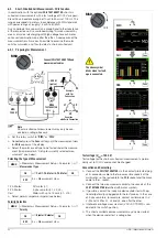
Connect the (discharged!) device under test to the sockets
with the measurement cables as shown.
➭
Measurement is started immediately.
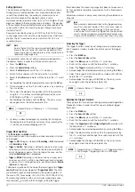
Improving Accuracy by means of Zero Balancing – Zero
Cable capacitance and junction capacitance can be eliminated in
all measuring ranges by means of zero balancing.
➭
Open the connected measurement cables to this end.
➭
Press the
Zero
softkey.
➭
Insofar as the value for
Zero
is less than a permissible threshold
of 0 to 50% of the measuring range, the
Zero
softkey is no lon-
ger grayed out in the display and the
Zero
function can be acti-
vated by pressing the
Zero
key.
➭
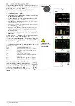
The value ascertained for
Zero
is saved and appears above the
measurement display. Automatic compensation of cable ca-
pacitance is activated for all subsequent measurements. This
value remains in memory even after the instrument has been
switched off.
➭
The value for Zero is retained when the instrument is switched
to a different measuring function. The correction or offset value
is deleted by pressing
Zero
once again, or when the instrument
is switched off. The value is cleared from the display.
Note
The “–” pole of polarized capacitors must be connected
to the “
” jack.
Resistors and semiconductor paths connected in parallel
to the capacitor distort measurement results!
Note
The “Setup for currently selected measurement” sub-
menu cannot be accessed for the capacitance measure-
ment because no further settings are provided for.
S–
A
V
Temp
m
/4
COIL
S+
S–
A
V
Temp
m
/4
COIL
S+
0 V!
!
+
–
Temp
30 nF/300 nF/
Measuring ranges:
+
–
3 μF
30 μF/300 μF
Func
Func
Func
Func
F
Temp. RTD
TEMP TC
Zero


