


OM-05724
JD Series
PAGE B - 3
INSTALLATION
Pump Motor Specifications
The motor furnished with this pump is a 60 Hz.,
Squirrel Cage, Induction Start, G‐R Frame Size No.
9; Class F Insulation Rated 155
_
C (311
_
F), 40
_
C
(104
_
F) ambient, plus 115
_
C (239
_
F) temperature
rise.
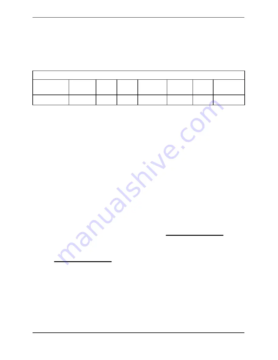
See Table B-1 for motor specifications.
TABLE B‐1. PUMP MOTOR SPECIFICATIONS
MODEL
VOLTAGE
SIZE
RPM
MOTOR
MAX
NO
LOCKED
H.P.
NUMBER
LOAD
LOAD
ROTOR
JD12AB60-E54
460/3
12”
/
PHASE
54
870
74.5A
33.0A
402.3A
PUMP INSTALLATION
Lifting
Pump unit weights will vary depending on the
mounting and drive provided. Check the shipping
tag on the unit packaging for the actual weight, and
use lifting equipment with appropriate capacity.
Drain the pump and remove all customer‐installed
equipment such as suction and discharge hoses
or piping before attempting to lift existing, installed
units.
Positioning the Pump
NOTE
Before installing and operating the pump, check
the direction of impeller rotation to ensure that the
pump is properly wired at the control box. See
IM
PELLER ROTATION
,
SECTION C.
This pump is designed to be operated mounted on
a stand with an optional suction elbow. See FIG
URE B-1 for a typical stand/elbow installation.
1. See FIGURE E-1 in
MAINTENANCE AND
REPAIR - SECTION E
, during pump installa
tion.
2. Install and secure the stand (26) in the floor of
the dry pit.
3. Secure the suction flange (150) to the suction
piping.
4. Secure the volute discharge flange to the sys
tem discharge piping.
Make certain that the pump and stand sit level in
the wet well.
Piping
NOTE
Refer to
PERFORMANCE CURVES
in
OPERA
TION - SECTION C
when determining the most ef
ficient piping installation.
The volute discharge is 12 inches in diameter. Ei
ther hose or rigid pipe may be used to make dis
charge connections.
Both suction and discharge lines must be inde
pendently supported to avoid vibration and strain
on the pump. For maximum pumping capacity,
keep the lines as short and straight as possible. El
bows and fittings used in a discharge line increase
friction losses; minimize their use.
It is recommended that a check valve or throttling
valve be installed in the discharge line to control si
phoning or back flow when the pump is shut off.


