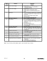
Note:
If any of the above listed problems persist, contact Gorbel® Customer Service.
Fault
Code
Failure
Possible
Causes
2
DC Bus Under Voltage
1.
Low AC line in.
2.
Transformer feeding AC in on the MLD is
undersized for the load.
3
DC Bus Over Voltage
1.
High AC line in.
2.
Regen circuit is not operating correctly.
3.
Regen resistor not connected correctly or has
failed.
4
IGBT Fault
1.
Too much weight being lifted by the unit (applies if
weight limit set greater than 185 pounds on a 150
pound unit).
2.
Loss of an internal power supply voltage.
3.
PWM logic error.
4.
Over current detected through IGBT.
5
IGBT Over Temperature
1.
IGBT is greater than 85 degrees C.
6
Over Current
1.
Over current detected through the current sensor.
2.
Too much weight being lifted by the unit (applies if
weight limit set greater than 185 pounds on a 150
pound unit).
3.
Wire Rope is bound.
4.
The motor is wired incorrectly.
5.
IGBT failure (applies if code will not reset with the
cycling of power).
7
Motor Over Temperature
1.
Motor has exceeded its upper temperature limit.
8
Safety Relay Failure
1.
Relay timing closing the motor brake and opening
the motor windings does not meet specified timing
requirements.
9
Unknown Source Reset
1.
CPU was reset, but not by power down or via the
JTAG programming port.
10
Missing Clock Caused Reset
1.
16 Mhz clock stopped.
11
Watchdog Timer Caused Reset
1.
The CPU has stopped running code feeding
watchdog timer.
12
XTAL Oscillator Startup Error
1.
The external 16 Mhz oscillator did not start.
13
Unexpected Hardware Configuration
1.
Mode switch does not match jumper or software
configuration.
2.
Handle pulled in during power up.
3.
Power interruption during operation.
18
4/04-Rev. S
®
Summary of Contents for 150 BX G-Force
Page 26: ...Figure A3 bottom Figure A4 top 150 BX Actuator Assembly 25 4 04 Rev S ...
Page 27: ...Figure A5 150 BX Actuator Assembly 26 4 04 Rev S ...
Page 28: ...Figure A6 150 BX Actuator Assembly 27 4 04 Rev S ...
Page 29: ...Figure A7 bottom Figure A8 top 150 BX Actuator Assembly 28 4 04 Rev S ...
Page 30: ...Figure A9 bottom Figure A10 top 150 BX Actuator Assembly 29 4 04 Rev S ...
Page 31: ...Figure A11 bottom Figure A12 top 150 BX Actuator Assembly 30 4 04 Rev S ...
Page 32: ...Figure A13 150 BX Actuator Assembly 31 4 04 Rev S ...
Page 33: ...Figure A14 150 BX Actuator Assembly 32 4 04 Rev S ...
Page 35: ...Figure B3 bottom Figure B4 top 300 380 BX Actuator Assembly 34 4 04 Rev S ...
Page 36: ...Figure B5 300 380 BX Actuator Assembly 35 4 04 Rev S ...
Page 37: ...Figure B6 300 380 BX Actuator Assembly 36 4 04 Rev S ...
Page 38: ...Figure B7 bottom Figure B8 top 300 380 BX Actuator Assembly 37 4 04 Rev S ...
Page 39: ...Figure B9 bottom Figure B10 top 300 380 BX Actuator Assembly 38 4 04 Rev S ...
Page 40: ...Figure B11 bottom Figure B12 top 300 380 BX Actuator Assembly 39 4 04 Rev S ...
Page 41: ...40 Figure B13 300 380 BX Actuator Assembly 4 04 Rev S ...
Page 42: ...Figure B14 300 380 BX Actuator Assembly 41 4 04 Rev S ...
Page 44: ...Figure C3 Standard Handle Assembly 43 4 04 Rev S ...
Page 45: ...Figure C4 Standard Handle Assembly 44 4 04 Rev S ...
Page 46: ...Figure C5 bottom Figure C6 top Standard Handle Assembly 45 4 04 Rev S ...
Page 47: ...Figure C7 bottom Figure C8 top Standard Handle Assembly 46 4 04 Rev S ...
Page 48: ...Figure C9 bottom Figure C10 top Standard Handle Assembly 47 4 04 Rev S ...
Page 49: ...Figure C11 bottom Figure C12 top Standard Handle Assembly 48 4 04 Rev S ...
Page 50: ...Figure C13 Standard Handle Assembly 49 4 04 Rev S ...
Page 52: ...Figure D3 bottom Figure D4 top Float Mode Handle Assembly 51 4 04 Rev S ...
Page 53: ...Figure D5 bottom Figure D6 top Float Mode Handle Assembly 52 4 04 Rev S ...
Page 54: ...Figure D7 bottom Figure D8 top Float Mode Handle Assembly 53 4 04 Rev S ...
Page 55: ...Figure D9 bottom Figure D10 top Float Mode Handle Assembly 54 4 04 Rev S ...
Page 56: ...Figure D11 Float Mode Handle Assembly 55 4 04 Rev S ...
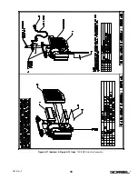
Page 58: ...Figure E2 Air Coil Cord Assembly Standard Float Mode 57 4 04 Rev S ...
Page 59: ...Figure E3 Remote Mount Coil Cord Standard Float Mode 58 4 04 Rev S ...
Page 60: ...Figure E4 Air Remote Mount Coil Cord Standard Float Mode 59 4 04 Rev S ...
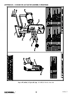
Page 61: ...APPENDIX F CONTROLS SCHEMATIC DRAWINGS Figure F1 Remote Load Cell Assembly 60 4 04 Rev S ...
Page 62: ...Figure F2 BX Controls Schematic 61 4 04 Rev S ...
Page 64: ...Figure G2 BX G Force 300 380 Overall Dimensions 63 4 04 Rev S ...
Page 67: ...Figure I2 300 380 Standard Inline Component Layout 66 4 04 Rev S ...
Page 68: ...Figure I3 Standard Remote Mount Component Layout 67 4 04 Rev S ...


