LIFT FUNCTIONALITY
Standard Operation:
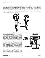
The Gorbel® G-Force® BX ILD is a servomotor driven, high speed, ergonomic materials
handling device. When the device is in the standard operational mode, the sliding handle of the hand controller
commands the z-axis direction and speed of the lift (
reference Diagram A
). The handle has a center neutral position
and can slide up and down to provide up and down speed commands to the control system. The further the handle is
displaced from the neutral position, the faster the servo movement to lift or lower the load. The operator lifts or
lowers the load by grasping the handle and moving it up or down as it it were an extension of the operator's arm. The
lift moves slightly slower when a heavy load is lifted, thereby giving the operator some feel for the weight of the load
and thus reducing inertial forces. When depressed, the operator present switch in the handle activates the
servomotor (
reference Diagram A
). Depressing the operator present switch also releases an electrically operated
mechanical failsafe holding brake in the motor.
Float Mode (System Option):
This mode is initiated by
simply pressing the Float Mode Enable button on the hand
controller. In this mode, the operator can simply handle the
load directly with either one or two hands and cause the
load to raise or lower by applying either an upward or
downward force on the load. This mode overrides the need
to depress the operator present switch. The greater the
force applied, the faster the load will move. There is a
standard setting in the controls that safely limits the
maximum speed of travel in Float Mode. Actuating the
operator present switch while in Float Mode will cause the
unit to exit float. While in Float Mode, the load cannot be
increased or decreased because this may cause unwanted
motion. Float Mode must be reinitiated each time the
weight of the live load is changed. The Float Mode enable
button is located on the face of the handle (
reference
Diagram B
).
Emergency Stop Button:
When depressed, the
Emergency Stop (E-Stop) button cuts off all power to the
Controls, and sets the mechanical fail-safe brake. The E-
Stop button is located on the face of the handle (
reference
Diagram B
). The G-Force® can’t operate until the E-Stop
has been reset.
Diagram A.
Sliding Handle - Operator Present Switch Lever.
Diagram B.
E-Stop and Float Mode
(optional) Buttons.
7
4/04-Rev. S
®
®
Summary of Contents for 150 BX G-Force
Page 26: ...Figure A3 bottom Figure A4 top 150 BX Actuator Assembly 25 4 04 Rev S ...
Page 27: ...Figure A5 150 BX Actuator Assembly 26 4 04 Rev S ...
Page 28: ...Figure A6 150 BX Actuator Assembly 27 4 04 Rev S ...
Page 29: ...Figure A7 bottom Figure A8 top 150 BX Actuator Assembly 28 4 04 Rev S ...
Page 30: ...Figure A9 bottom Figure A10 top 150 BX Actuator Assembly 29 4 04 Rev S ...
Page 31: ...Figure A11 bottom Figure A12 top 150 BX Actuator Assembly 30 4 04 Rev S ...
Page 32: ...Figure A13 150 BX Actuator Assembly 31 4 04 Rev S ...
Page 33: ...Figure A14 150 BX Actuator Assembly 32 4 04 Rev S ...
Page 35: ...Figure B3 bottom Figure B4 top 300 380 BX Actuator Assembly 34 4 04 Rev S ...
Page 36: ...Figure B5 300 380 BX Actuator Assembly 35 4 04 Rev S ...
Page 37: ...Figure B6 300 380 BX Actuator Assembly 36 4 04 Rev S ...
Page 38: ...Figure B7 bottom Figure B8 top 300 380 BX Actuator Assembly 37 4 04 Rev S ...
Page 39: ...Figure B9 bottom Figure B10 top 300 380 BX Actuator Assembly 38 4 04 Rev S ...
Page 40: ...Figure B11 bottom Figure B12 top 300 380 BX Actuator Assembly 39 4 04 Rev S ...
Page 41: ...40 Figure B13 300 380 BX Actuator Assembly 4 04 Rev S ...
Page 42: ...Figure B14 300 380 BX Actuator Assembly 41 4 04 Rev S ...
Page 44: ...Figure C3 Standard Handle Assembly 43 4 04 Rev S ...
Page 45: ...Figure C4 Standard Handle Assembly 44 4 04 Rev S ...
Page 46: ...Figure C5 bottom Figure C6 top Standard Handle Assembly 45 4 04 Rev S ...
Page 47: ...Figure C7 bottom Figure C8 top Standard Handle Assembly 46 4 04 Rev S ...
Page 48: ...Figure C9 bottom Figure C10 top Standard Handle Assembly 47 4 04 Rev S ...
Page 49: ...Figure C11 bottom Figure C12 top Standard Handle Assembly 48 4 04 Rev S ...
Page 50: ...Figure C13 Standard Handle Assembly 49 4 04 Rev S ...
Page 52: ...Figure D3 bottom Figure D4 top Float Mode Handle Assembly 51 4 04 Rev S ...
Page 53: ...Figure D5 bottom Figure D6 top Float Mode Handle Assembly 52 4 04 Rev S ...
Page 54: ...Figure D7 bottom Figure D8 top Float Mode Handle Assembly 53 4 04 Rev S ...
Page 55: ...Figure D9 bottom Figure D10 top Float Mode Handle Assembly 54 4 04 Rev S ...
Page 56: ...Figure D11 Float Mode Handle Assembly 55 4 04 Rev S ...
Page 58: ...Figure E2 Air Coil Cord Assembly Standard Float Mode 57 4 04 Rev S ...
Page 59: ...Figure E3 Remote Mount Coil Cord Standard Float Mode 58 4 04 Rev S ...
Page 60: ...Figure E4 Air Remote Mount Coil Cord Standard Float Mode 59 4 04 Rev S ...
Page 61: ...APPENDIX F CONTROLS SCHEMATIC DRAWINGS Figure F1 Remote Load Cell Assembly 60 4 04 Rev S ...
Page 62: ...Figure F2 BX Controls Schematic 61 4 04 Rev S ...
Page 64: ...Figure G2 BX G Force 300 380 Overall Dimensions 63 4 04 Rev S ...
Page 67: ...Figure I2 300 380 Standard Inline Component Layout 66 4 04 Rev S ...
Page 68: ...Figure I3 Standard Remote Mount Component Layout 67 4 04 Rev S ...


