<
2
>
It is required that the power cord can be easily plugged in and unplugged from the
power supply and power outlet. Please keep the power cord and plug clean and
undamaged, otherwise there may be a risk of electric shock or fire.
Note: If the battery is replaced incorrectly, there is a risk of explosion. Only
use the replacement of the same or equivalent type recommended by
the manufacturer. The used battery will cause environmental
pollution. Replace the old battery and follow the instructions.
Keep the computer away from electromagnetic fields.
Stay away from electronic noise caused by high-frequency safety equipment such
as large air-conditioning fans, large motor TV stations, and transmission towers.
Do not plug or unplug the backplane or move the computer while the computer is
running. Doing so may cause the computer to crash or damage the components.
Please try to avoid frequent restart or switch on and off to extend the life of your
computer.
Please keep the environment clean and avoid dust. The working temperature of
the equipment is 10°C~35°C and the humidity is 35%~80%.
Please promptly back up important data. Gooxi Technology Co., Ltd. is not
responsible for data loss caused by any situation.
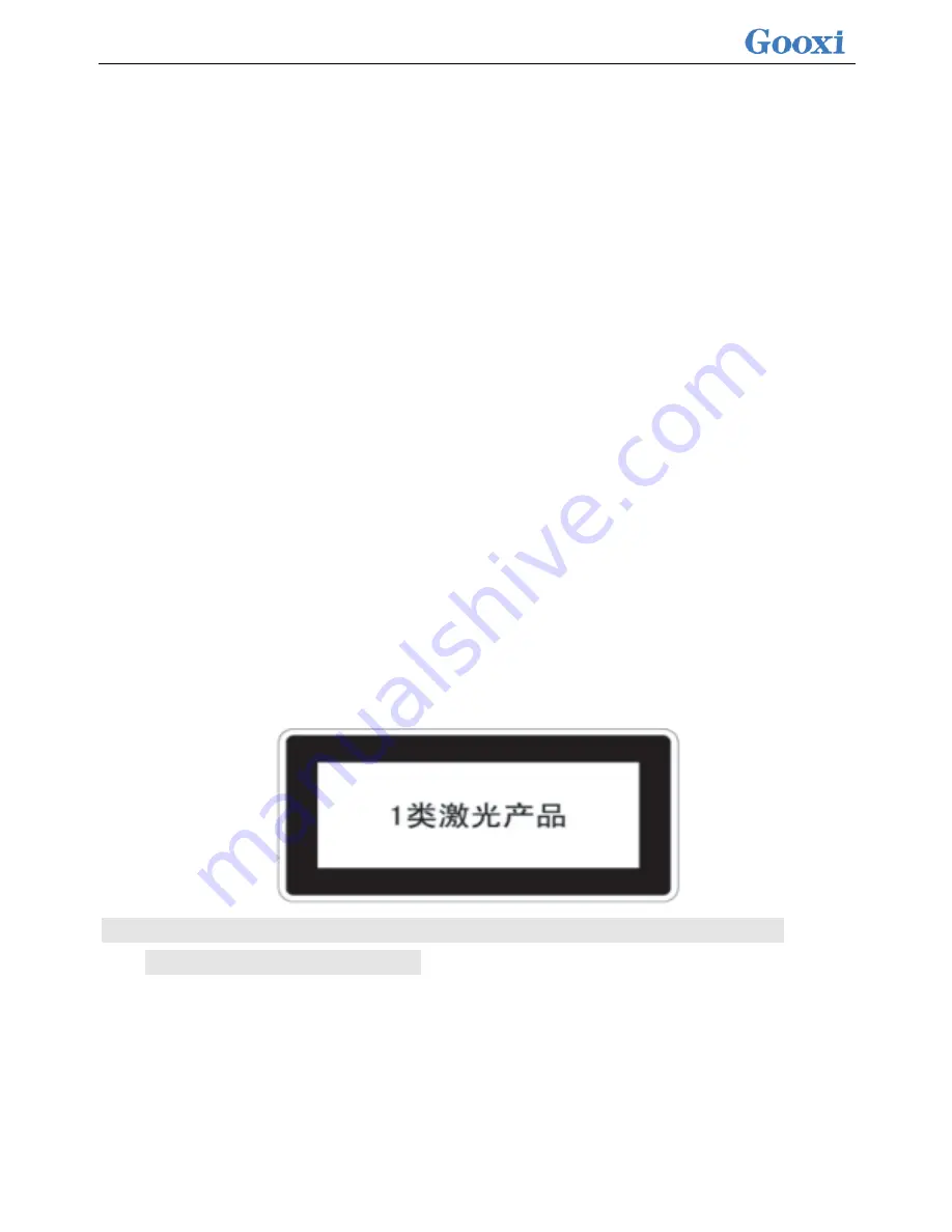
This product uses an optical drive as a Class 1 laser device.
1.2 Product toxic and hazardous substances or elements name and
content identification table
During the 10-year environmental protection use period, toxic or hazardous
substances or elements contained in the product will not leak or mutate under
normal use conditions. Users of electronic information products will not cause
serious environmental pollution or Personal and property causes serious damage.
Summary of Contents for Purley Platform 1U
Page 1: ...Purley Platform 1U L Shape Server Product Manual REV 1 0...
Page 4: ...functions Chapter 7 RAID Setup Instructions...
Page 8: ...Chapter 10 Product Specifications 283...
Page 18: ...10 2 3 System model specifications 1U4 bay 3 5 inch disk model positive...
Page 53: ...45...
Page 58: ...50...
Page 78: ...70...
Page 79: ...71...
Page 80: ...72 6 2 5ALL CPU Information Display the system CPU model version and other details...
Page 86: ...78 Disabled Off Default Disabled 6 2 10 SIO Configuration...
Page 109: ...101 6 2 24 Per Socket Configuration menu...
Page 115: ...107 6 2 27 Memory Topology menu Displays the current system memory details...
Page 160: ...152 d Enter the RAID card configuration interface as shown in the following figure...
Page 162: ...154 b Enter the screen shown below select Select RAID Level set the RAID level and press Enter...
Page 163: ...155 c Select Selcect Physical Disks to enter the RAID page of the selected group RAID...
Page 165: ...157 e Change Confirm to Enabled and select Yes to complete RAID configuration...
Page 168: ...160 Delete RAID a Select Virtual Disk Management and press enter...
Page 169: ...161 b Select Select Virtual Disk Operations and press enter...
Page 170: ...162 c Select Delete Virtual Disk and press enter...
Page 171: ...163 d Change Confirm to Enabled check Yes and press enter to finish deleting RAID...
Page 179: ...171 d Go to the screen shown in Figure 3 5 Select Go and press Enter Figure 3 5 Select Go...
Page 197: ...189 d Go to the screen shown in Figure 3 21 Choose Go and press Enter Figure 3 21 Select Go...
Page 203: ...195 d Go to the screen shown in Figure 2 38 Choose Go and press Enter Figure 2 38 Select Go...
Page 209: ...201 d Go to the Figure 2 44 screen Choose Go and press Enter Figure 2 44 Select Go...
Page 214: ...206 d Go to the screen shown in Figure 2 49 Choose Go and press Enter Figure 2 49 Select Go...
Page 225: ...217 d Go to the Figure 2 60 screen Choose Go and press Enter Figure 2 60 Select Go...
Page 232: ...224 e Go to the screen shown in Figure 2 67 Choose Go and press Enter Figure 2 67 Select Go...
Page 239: ...231 e Go to the interface shown in Figure 2 74 Choose Go and press Enter Figure 2 74 Select Go...
Page 245: ...237 d Go to the screen shown in Figure 2 80 Choose Go and press Enter Figure 2 80 Select Go...
Page 250: ...242 i Go to the screen shown in Figure 2 85 Choose OK and press Enter Figure 2 85 Select OK...
Page 289: ...281 Diagram3 5 KVM interface...
Page 293: ...285 Figure 3 9 SOL operation interface...
Page 301: ...293...


