<
268
>
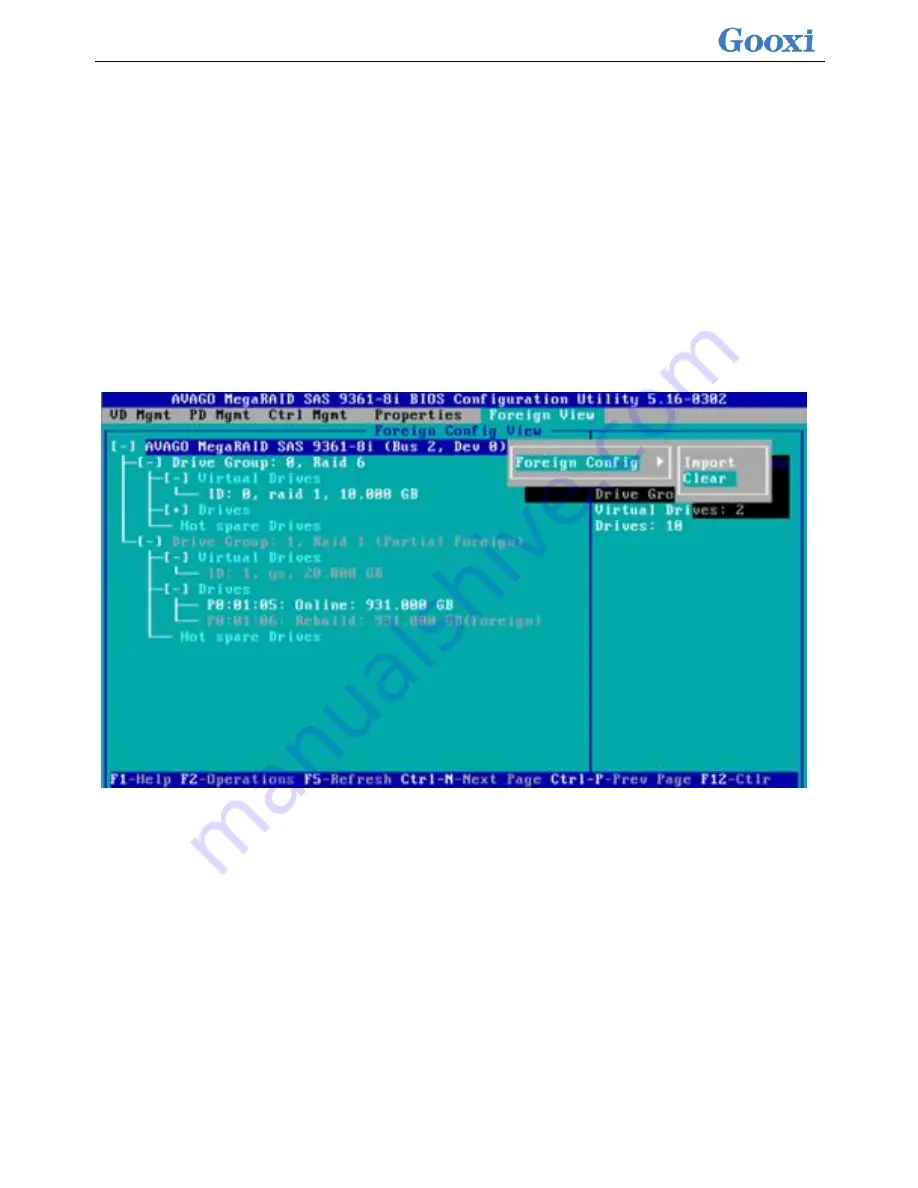
This function is used to clear the RAID residue information in the disk so that the disk can
be reused to configure RAID. This feature is commonly used for disks that have the
Unconfigured Bad mode.
a)
Switch the disk mode Unconfigured Bad to Unconfigured Good.
b)
As shown in Figure 2-118, in the Foreign View interface, select the RAID card, press
F2, select Foreign Config->Clear, and press Enter.
Figure 2-118 Select Foreign Config->Clear
c)
In the pop-up dialog box shown in Figure 2-119, select OK and press Enter to finish
clearing disk RAID information.
Figure 2-119 Confirm Clear
Summary of Contents for Purley Platform 1U
Page 1: ...Purley Platform 1U L Shape Server Product Manual REV 1 0...
Page 4: ...functions Chapter 7 RAID Setup Instructions...
Page 8: ...Chapter 10 Product Specifications 283...
Page 18: ...10 2 3 System model specifications 1U4 bay 3 5 inch disk model positive...
Page 53: ...45...
Page 58: ...50...
Page 78: ...70...
Page 79: ...71...
Page 80: ...72 6 2 5ALL CPU Information Display the system CPU model version and other details...
Page 86: ...78 Disabled Off Default Disabled 6 2 10 SIO Configuration...
Page 109: ...101 6 2 24 Per Socket Configuration menu...
Page 115: ...107 6 2 27 Memory Topology menu Displays the current system memory details...
Page 160: ...152 d Enter the RAID card configuration interface as shown in the following figure...
Page 162: ...154 b Enter the screen shown below select Select RAID Level set the RAID level and press Enter...
Page 163: ...155 c Select Selcect Physical Disks to enter the RAID page of the selected group RAID...
Page 165: ...157 e Change Confirm to Enabled and select Yes to complete RAID configuration...
Page 168: ...160 Delete RAID a Select Virtual Disk Management and press enter...
Page 169: ...161 b Select Select Virtual Disk Operations and press enter...
Page 170: ...162 c Select Delete Virtual Disk and press enter...
Page 171: ...163 d Change Confirm to Enabled check Yes and press enter to finish deleting RAID...
Page 179: ...171 d Go to the screen shown in Figure 3 5 Select Go and press Enter Figure 3 5 Select Go...
Page 197: ...189 d Go to the screen shown in Figure 3 21 Choose Go and press Enter Figure 3 21 Select Go...
Page 203: ...195 d Go to the screen shown in Figure 2 38 Choose Go and press Enter Figure 2 38 Select Go...
Page 209: ...201 d Go to the Figure 2 44 screen Choose Go and press Enter Figure 2 44 Select Go...
Page 214: ...206 d Go to the screen shown in Figure 2 49 Choose Go and press Enter Figure 2 49 Select Go...
Page 225: ...217 d Go to the Figure 2 60 screen Choose Go and press Enter Figure 2 60 Select Go...
Page 232: ...224 e Go to the screen shown in Figure 2 67 Choose Go and press Enter Figure 2 67 Select Go...
Page 239: ...231 e Go to the interface shown in Figure 2 74 Choose Go and press Enter Figure 2 74 Select Go...
Page 245: ...237 d Go to the screen shown in Figure 2 80 Choose Go and press Enter Figure 2 80 Select Go...
Page 250: ...242 i Go to the screen shown in Figure 2 85 Choose OK and press Enter Figure 2 85 Select OK...
Page 289: ...281 Diagram3 5 KVM interface...
Page 293: ...285 Figure 3 9 SOL operation interface...
Page 301: ...293...


