background image

18

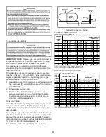
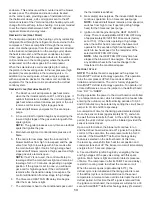
3.  Refer to the superheat table provided for proper 

system superheat. Add charge to lower superheat or 

recover charge to raise superheat.


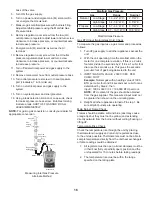
Superheat Formula = Suct. Line Temp. - Sat. Suct. 

Temp.

65

70

75

80

85

100

-

-

-

10

10

95

-

-

10

10

10

90

-

-

12

15

18

85

-

10

13

17

20

80

-

10

15

21

26

75

10

13

17

25

29

70

10

17

20

28

32

65

13

19

26

32

35

60

17

25

30

33

37

Ambient 

Condenser Inlet 

Temp (°F Drybulb)

Return Air Temp. (°F Drybulb)

EXAMPLE:

a. Suction Pressure = 143
b. Corresponding Temp. °F. = 50
c. Thermometer on Suction Line = 59°F.
To obtain the degrees temperature of superheat, subtract 

50.0 from 59.0°F.
The difference is 9° Superheat. The 9° Superheat would 

fall in the ± range of allowable superheat.

CHECKING SUBCOOLING

Refrigerant liquid is considered subcooled when its 

temperature is lower than the saturation temperature 

corresponding to its pressure. The degree of subcooling 

equals the degrees of temperature decrease below the 

saturation temperature at the existing pressure.

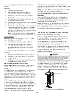
1.  Attach an accurate thermometer or preferably a 

thermocouple type temperature tester to the liquid 

line close to the pressure switch.

2.  Install a high side pressure gauge on the liquid 

access fitting.

3.  Record the gauge pressure and the temperature of 

the line.

4.  Compare the hi-pressure reading to the “Required 

Liquid Line Temperature” chart. Find the hi-pressure 

value on the left column. Follow that line right to 

the column under the design subcooling value. 

Where the two intersect is the required liquid line 

temperature. Alternately you can convert the liquid 

line pressure gauge reading to temperature by 

finding the gauge reading in Temperature - Pressure 

Chart and reading to the left, find the temperature in 

the °F. Column.

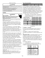
LO COOL

HI COOL

LO HEAT

HI HEAT

U6

U7

U4

U5

U3

K2

K1

P1

ECON

STAGE

DELAY

SPEEDUP

SW1

FAULT

RECALL

BLOWER

OFF DELAY

F1

R

C W1 W2G Y1 Y2

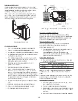
Control Board (Top)

Unit Shutdown

1.  Set the thermostat to lowest setting.
2.  Turn off the electrical power supply to the unit.
3.  Remove the heat exchanger door on the side of the 

unit by removing screws.

4.  Move the gas control valve switch to the OFF 

position.  Do not force.

5.  Close manual gas shutoff valve external to the unit.
6.  Replace the heat exchanger door on the unit.
7.  If cooling and/or air circulation will be  desired, turn 

ON the electrical power.

Cooling Start-up

NOTE:

 Check all manual reset limit controls in heating 

circuit if cooling mode does not operate.

SUPERHEAT

Checking superheat

Refrigerant gas is considered superheated whenever its 

temperature is higher than the saturation temperature 

corresponding to its pressure. The degree of superheat 

equals the degrees of temperature increase above the 

saturation temperature at existing pressure. 

1.  Run system at least 10 minutes to allow pressure to 

stabilize.

2.  Temporarily install thermometer on suction (large) 

line near compressor with adequate contact and 

insulate for best possible reading.

Summary of Contents for APD 14 M Series

Page 1: ...l the product safely and to educate the customer on its safe use Goodman Manufacturing Company L P 19001 Kermier Rd Waller TX 77484 www goodmanmfg com or www amana hac com 2011 2018 2021 Goodman Manuf...

Page 2: ...23 Heating Timing Chart 23 Cooling heat pump Timing Chart 23 Unit Dimensions 24 WIRING DIAGRAM 25 Minimum Clearances 27 Recommended Filter Sizes 27 Blower Performance Data 29 START UP CHECKLIST 30 TO...

Page 3: ...amage personal injury or loss of life AVERTISSEMENT RISQUE D INCENDIE OU D EXPLOSION Si les consignes de s curit ne sont pas suivies la lettre cela peut entra ner la mort de graves blessures ou des do...

Page 4: ...moyen des essais d crits ci dessus les portes les fen tres les ventilateurs les registres de foyer et tous les autres appareils de combustion aliment s au gaz doivent tre remis dans leur tat initial l...

Page 5: ...IER ROAD Houston Texas 77484 877 254 4729 GENERAL INFORMATION This unit is approved for outdoor installation ONLY To assure that your unit operates safely and efficiently it must be installed operated...

Page 6: ...al fresh air damper motorized fresh air damper to become blocked by snow or debris In some climates or locations it may be necessary to elevate the unit to avoid these problems Damper must be in open...

Page 7: ...gas and gas input rating Make sure the unit is equipped to operate on the type of gas available Conversion to LP gas is permitted with the use of the factory authorized conversion kit LPM 08 Natural...

Page 8: ...long 5 Use two pipe wrenches when making connection to the gas valve to keep it from turning 6 Install a manual shut off valve in a convenient location within six feet of unit between the meter and t...

Page 9: ...e based on 1 PSIG Pressure Drop at 10 PSIG Setting Capacities in 1 000 BTU HR 3 8 1 2 5 8 3 4 7 8 1 2 3 4 30 309 700 1 303 2 205 3 394 1 843 3 854 40 265 599 1 115 1 887 2 904 1 577 3 298 50 235 531 9...

Page 10: ...Exercise caution when servicing as only one leg of the power supply is broken with the contractor High Voltage Wiring Rated Voltage Minimum Supply Voltage Maximum Supply Voltage 208 230V 197 253 The u...

Page 11: ...ming the installation In some installations it will be necessary to change the blower speed to provide proper air flow Horizontal Air Flow Single phase models are shipped without horizontal duct cover...

Page 12: ...FLUE HOOD LIP Installation Combustion Air Intake Hood 1 Locate the second hood 2 Using the three screws provided attach the hood with the opening facing down to the heat exchanger access door CONDENSA...

Page 13: ...it delivers heat to the conditioned space until the thermostat is satisfied 8 Gas valve s de energizes The induced draft blower continues operation for a 30 second post purge NOTE Induced draft blower...

Page 14: ...ing etc In general 400 CFM per ton of cooling capacity is a rule of thumb Some applications depending on the sensible and latent capacity requirements may need only 350 CFM or up to 425 CFM per ton Ch...

Page 15: ...supply to the unit 12 Set the thermostat to desired setting On Off Switch Inlet PressureBoss High Fire Coil Terminal HI LowFire Regulator Adjust Manometer Manometer Hose A HighFire Regulator Adjust R...

Page 16: ...0 W C High Stage 9 7 10 3 W C 10 0 W C Manifold Gas Pressure Gas BTU Input Natural Gas Only Check To measure the gas input use a gas meter and proceed as follows 1 Turn off gas supply to all other ap...

Page 17: ...ING SPEED TAPS ON THE BLOWER MOTOR Refer to the wiring diagram and airflow data in the appendix to verify speed tap settings Depending upon the model blower speeds are changed at the indoor blower The...

Page 18: ...column Follow that line right to the column under the design subcooling value Where the two intersect is the required liquid line temperature Alternately you can convert the liquid line pressure gauge...

Page 19: ...d in the return air duct s or return air filter grille s Consult with your installing dealer for the actual location of the return air filter s for your unit Dirty filters are the most common cause of...

Page 20: ...off Burner Flame At least once a year prior to or during the heating season make a visual check of the burner flames NOTE This will involve removing and reinstalling the heat exchanger door on the un...

Page 21: ...RESSURE SWITCH 3 FLASHES 2 FLASHES 4 FLASHES 5 FLASHES FALSE FLAME DETECTED OPEN LIMIT SWITCH WITHOUT INDUCER ON PRESSURE SWITCH OPEN CHECK FOR SHORTS IN FLAME SENSOR WIRING NORMAL FLAME PRESENT DIAGN...

Page 22: ...3 Flashes Pressure Switch Stuck Closed 4 Flashes Thermal Protection Device Open 5 Flashes Flame Detected with Gas Valve Closed 6 Flashes Short Cycle Compressor Delay Cooling Only 7 Flashes Limit Open...

Page 23: ...23 UNIT DIMENSIONS...

Page 24: ...CER L2 PARK 24VAC COM 5 4 3 2 1 1 2 3 5 6 7 8 9 EM N G L T5 T4 T3 T2 T1 C 1 2 6 4 1 FS LS M C H1 RS VM ALS PS GV IGN H C F LO HEAT 6 3 1 2 4 5 OR BL PU YL OR BR OR P1 PIN 3 P1 PIN 5 P1 PIN 9 P1 PIN 2...

Page 25: ...ED AS AN ALTERNATE CONFIGURATION LINE VOLTAGE OPTIONAL HIGH VOLTAGE HIGH VOLTAGE FIELD WIRING LOW VOLTAGE LOW VOLTAGE BK BLACK WIRE CODE PK PINK OR ORANGE GR GREEN BR BROWN BL BLUE RD RED WH WHITE YL...

Page 26: ...1 1 20 x 25 x 1 1 25 x 25 x1 2 20 x 20 x 1 Clearance in accordance with local installation codes the requirements of the gas supplier and the manufacturer s instal lation instructions D gaugement conf...

Page 27: ...08 144 1023 149 1285 242 0 3 922 165 49 1206 289 50 956 151 976 157 1237 250 0 4 886 173 51 1164 302 52 908 158 928 164 1189 257 0 5 835 182 54 1131 314 53 857 166 880 172 1141 265 0 6 781 188 58 1086...

Page 28: ...9 137 49 1260 213 55 1317 230 1317 230 1453 269 0 2 1008 144 52 1212 221 57 1269 237 1269 237 1405 277 0 3 956 151 54 1165 229 59 1221 245 1221 245 1357 284 0 4 908 158 57 1117 236 62 1174 253 1174 25...

Page 29: ...0 1275 347 59 974 204 1261 338 1612 450 0 5 871 204 65 1224 357 61 910 212 1211 343 1563 458 0 6 811 213 X 1172 364 64 847 220 1168 356 1514 466 0 7 753 210 X 1130 379 X 784 227 1111 373 1466 474 0 8...

Page 30: ...LP Liquid Propane Residential Package Outdoor Section ELECTRICAL Supply Voltage Measure L1 and L2 Voltage L1 L2 Compressor Amps Condenser Fan Amps PRESSURES TEMPERATURES Suction Circuit Pressure Suct...

Page 31: ...31 THIS PAGE IS INTENTIONALLY LEFT BLANK...

Page 32: ...trademark of Maytag Corporation or its related companies and is used under license All rights reserved NOTE SPECIFICATIONS AND PERFORMANCE DATA LISTED HEREIN ARE SUBJECT TO CHANGE WITHOUT NOTICE Quali...

Reviews: