All contents copyright 2014, GoldWing RC Version 2.0, Feb 2014
GoldWing RC
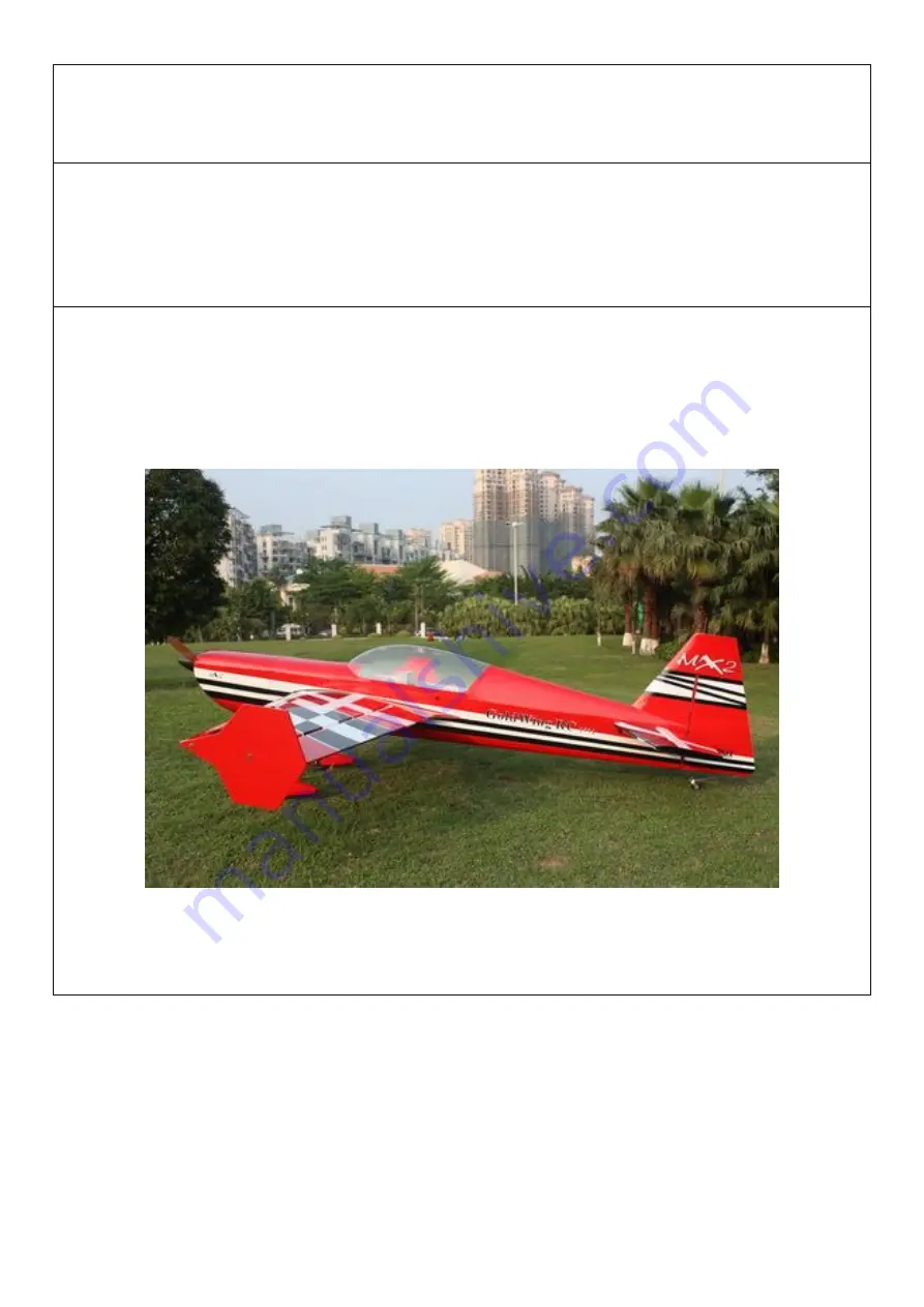
MX2 50CC V4
Giant Scale Aerobatic Aircraft
Page 1: ...All contents copyright 2014 GoldWing RC Version 2 0 Feb 2014 GoldWing RC MX2 50CC V4 Giant Scale Aerobatic Aircraft...
Page 2: ...ailerons Also the new Carbon fibre tail wheel assembly with CNC machined metal parts including the aluminium tail wheel hub We hope you will enjoy your new giant scale aircraft as much as we have The...
Page 3: ...rmation package call 1 800 435 9262 ext 292 or visit the AMA website at www modelaircraft org Or if you are in any other country please contact the appropriate body By the act of using the final assem...
Page 4: ...tents copyright 2014 GoldWing RC Version 2 0 Feb 2014 Larger aileron and elevator design Up to 60 degrees of throw on all control surfaces for excellent 3D aerobatic flying High quality ball link asse...
Page 5: ...All contents copyright 2014 GoldWing RC Version 2 0 Feb 2014 Aluminium hub rubber wheels Improved axles the material of the axle is now stainless steel Servo lead safety clips...
Page 6: ...All contents copyright 2014 GoldWing RC Version 2 0 Feb 2014 High performance cap head bolts Flat nylon hinges for inproved flying strength Honeycomb board carton packing for safer transportation...
Page 7: ...All contents copyright 2014 GoldWing RC Version 2 0 Feb 2014 Pre hinged control surfaces Pre assembled and mounted gas tank Installed servo wire guide tube...
Page 8: ...All contents copyright 2014 GoldWing RC Version 2 0 Feb 2014 Extra covering provided for small repairs genuine Ultracote Oracover Removable rudder Side force generators included...
Page 9: ...ts copyright 2014 GoldWing RC Version 2 0 Feb 2014 CNC anodized aluminum canopy bolts Full length tuned pipe design inside the fuselage Carbon Fiber accessories version Extra strength carbon fiber con...
Page 10: ...ontents copyright 2014 GoldWing RC Version 2 0 Feb 2014 One piece air foiled carbon fiber landing gear Carbon fiber tail wheel assembly with CNC machined metal parts including the aluminium tail wheel...
Page 11: ...All contents copyright 2014 GoldWing RC Version 2 0 Feb 2014 Increased diameter carbon fiber wing tube over previous versions Carbon fiber stab tube...
Page 12: ...All contents copyright 2014 GoldWing RC Version 2 0 Feb 2014 Scheme A White black green...
Page 13: ...All contents copyright 2014 GoldWing RC Version 2 0 Feb 2014 Scheme C Red white black...
Page 14: ...parts of this kit with care so you do not damage any of the structure or covering Inspect all the parts for any shipping damage and report any issues to as soon as you can Make sure you have a flat a...
Page 15: ...and do not normally require this step Sealing the hinge gaps is therefore left as an option for the modeler Please verify the accessories before commencing assembly Carbon Fiber control Horns Bag No K...
Page 16: ...BG3 Four 3x60mm pushrods for ailerons One 3x165mm pushrods rudder Pull push style Pull pull assembly kits for the rudder Bag No KA05CD Ball link assembly Bag No KAG00131 8 for ailerons and elevators A...
Page 17: ...eb 2014 Servo lead safety clips 6 pcs Bag No KAG0021 3 5 Alu main wheels 2pcs Bag No KAG0159 New stainless steel Axle kits Bag No KA05CH Carbon fibre tail wheel assembly with CNC machined metal parts...
Page 18: ...yright 2014 GoldWing RC Version 2 0 Feb 2014 4mm ALU canopy bolts Bag No KAG0043 Extra covering provided for small repairs Wrench set Bag No KA05CE Side force generators 4 x 3x20mm hex bolts 4 x washe...
Page 19: ...b 2014 Bolts for landing gear 4 4x20mm hex bolts 4 washers 4 M4 stainless steel self locking nuts Bolts washers for cowl 4 3x16mm Hexagon bolts and 4 washers Spares bag Two spare aluminum hand twist b...
Page 20: ...ng away from the slots in the rudder and trial fit the two control horns 2 Mix up some 30 minute epoxy and coat the inside of the slots and the center of the control horns Hint a scrap piece of 1 16 p...
Page 21: ...the model assembled before choosing your servo placement 5 The MX2 is supplied with a high quality set of pull pull cables and ball links 6 Install your rudder servo into the precut locations in the f...
Page 22: ...er centered adjust the cable length as tight as possible while checking the ball link position over the servo arm When satisfied with the position pinch the cable around the threaded coupler and then...
Page 23: ...ights as they may stretch slightly from the initial installation 11 The MX2 also provides pull push style for rudder Below is picture of pull push style linkage set 12 Cut off excess carbon fiber rudd...
Page 24: ...ever this plane s landing gear is assembled the same way 1 Locate the supplied main and tail wheel landing gear parts and sort them out on your workbench 2 Bolt the main gear to the bottom of the fuse...
Page 25: ...anding gear and tighten the nylon insert lock nut Install one wheel collet onto the axle Use a second wheel collar as a guide to leave a gap on the inboard of the axle Use a small drop of thread lock...
Page 26: ...lock to secure the bolts in place Repeat the above steps for the other side 6 Use your finger to find the three holes at the bottom of the fuselage Using a knife clear the holes and fix the tailwheel...
Page 27: ...l contents copyright 2014 GoldWing RC Version 2 0 Feb 2014 8 The following is a picture of correctly installed tail wheel assembly NOTE One spare tail wheel spring is included in the spare hardware pa...
Page 28: ...in this manual however this plane s wings is assembled the same way 1 Aileron push rod linkage set 3mmx60mm Pushrods for aileron 2 Locate the slots for the aileron control horn and remove the covering...
Page 29: ...0 Feb 2014 3 Rough the area of the horn that will be glued in place 4 Using 30 minute epoxy glue the horn and plate into the aileron REPEAT FOR THE OTHER SIDE 5 A string is pre placed in the wing to...
Page 30: ...Feb 2014 6 Connect extension servo wire secure with safe clips 7 Tie up servo extension with the string and then pull it through the wing 8 Screw holes for servo mounting are pre drilled by laser in...
Page 31: ...ldWing RC Version 2 0 Feb 2014 9 Locate the included aluminum long servo arm enlarge control holes with 3mm drill bit 10 Using the pushrods connect the servo arm to the horn Remember that on the pushr...
Page 32: ...he pushrod to the appropriate length REPEAT FOR THE OTHER SIDE ELEVATOR ASSEMBLY NOTE There are pictures of different planes in this manual however this plane s elevator is assembled the same way 1 Pu...
Page 33: ...e horn that will be glued inside the elevator 4 Using plenty of 30 minute epoxy fit the horn and plate into place Use a ball joint and bolt to hold the horn in place while drying REPEAT FOR THE OTHER...
Page 34: ...er to harden the holes with thin Cyano 7 Place the servo arm back onto the servo remembering to centre Use nutlock on the servo arm screw 8 Fit the pushrod in place remembering one end is reverse thre...
Page 35: ...are provided in the kit for both DA 50 and 60 along with the 3W 50 cc Select the correct guide for your engine and mark and drill the mounting holes and cut out the center as indicated Notice that the...
Page 36: ...ount it is on the side of the engine box Secure the pickup lead and ignition wires with zip ties so that they do not vibrate or touch any hot part of the engine or exhaust 5 Assemble the throttle serv...
Page 37: ...ed on the fuselage side opposite your ignition switch Make sure your vent line does not come close to any hot exhaust part such as the muffler or canister GW recommends the use of small zip ties or fu...
Page 38: ...attention to vibration mounts if required and air flow requirements Trial fit your exhaust system now and work out any additional supports but do not permanently install the system until you fit the c...
Page 39: ...ng iron to open up the holes COWLING INSTALLATION NOTE There are pictures of different planes in this manual however this plane s cowling is assembled the same way 1 With the engine fitted tape a piec...
Page 40: ...hin the cowl area then use the same method Depending on the amount of cooling required for your engine a template for louvers in the bottom of the cowl has been provided Use a dremel tool to remove th...
Page 41: ...GoldWing RC Version 2 0 Feb 2014 Labels are provided for aligning the drill holes for the cowl Stick then on without the cowl mark the hole Fit the cowl then press back down The hole will then show t...
Page 42: ...sure all wires are top quality and connectors are tight and display no loose pins or frayed wires Servo clips are provided in the kit for your convenience These servo clips can even be glued to the wo...
Page 43: ...dual rates at levels that suit your flying style If you find that you require tail weight and cannot move parts around the aircraft a rear hatch has been added Glue in the inner ring once the coverin...
Page 44: ...b 2014 Then install pull pull ball links on control horns Hook up the tail wheel spring 3 Installation of Elevators Connect servo extension wire secure with safe clips Attach elevators with 3x12mm Hex...
Page 45: ...ut will loosen after some with use Guide your servo wires into the fuselage openings and connect to the correct aileron channels Servo clips are highly recommended Once you have the wings fully seated...
Page 46: ...ne is not plugged or capped With the canopy off this is a good time to check for any fuel leaks 7 Position the canopy in place and tighten ALU canopy bolts Be sure to use the supplied rubber washers u...
Page 47: ...with the engine off and running Be sure all surfaces are moving in the correct direction and the correct amount for your flying setup 10 You are now ready for your maiden flight Good luck and enjoy y...
Page 48: ...All contents copyright 2014 GoldWing RC Version 2 0 Feb 2014 For JR servo 23T 47mm 1 75in Single No KAG0S73J 100mm 4in Dual No KAG0D73J 3 5in C F Spinner No KAG0135 Wingbags for 50CC No KAG0094...
Page 49: ...All contents copyright 2014 GoldWing RC Version 2 0 Feb 2014 www goldwingrc com...