IM054B2 – June 2010
14
5
1
23
22
21
13
16
7
17
19
24
20
18
15
8
12
10
6
29
2
27
26
31
33
32
11
9
25
4
OF
F
N
O
28
11.
DRAWINGS - SPARE PARTS SA-48FF
MODEL:
SA – 48FF
Page 1: ...RIES HEAVY DUTY SALAMANDERS PROUDLY AUSTRALIAN MADE INSTALLATION PROCEDURE USER MANUAL SERVICE INSTRUCTION MODELS SA MODELS SA MODELS SA MODELS SA 36 36 36 36FF FF FF FF SA SA SA SA 48 48 48 48FF FF FF FF GAS APPROVAL NO 2202 ESTABLISHED 1911 The Cooking Equipment Professionals www goldsteineswood com au ...
Page 2: ...NING Page 5 4 OPERATING INSTRUCTIONS Page 6 5 BRACKET POSITIONING Page 7 6 STAND MOUNTING OPTIONS Page 8 7 TECHNICAL DATA Page 9 8 SERVICING Page 10 9 TROUBLE SHOOTING Page 11 10 DRAWING SPARE PARTS SA 36 Page 12 13 11 DRAWING SPARE PARTS SA 48 Page 14 15 12 WARRANTY Page 16 13 BRANCHES Page 17 ...
Page 3: ...EIN SALAMANDER MODELS SA36FF SA48FF GOLDSTEIN SALAMANDERS are designed to give long and satisfactory service and incorporate the best possible materials and workmanship Proper installation adjustment and preventative maintenance are vitally important if efficiency and appearance are to be maintained Read these instructions carefully as they contain important safety information regarding the instal...
Page 4: ...2 Fix salamander stand brackets in desired position 3 Mount salamander onto stand brackets Ensure that there is a 50mm clearance between the rear and sides of the salamander and any combustible material 4 Have a licensed gas fitter or your Gas Company connect the appliance to the mains supply Location of the 19mm B S P gas fitting is seen on page 10 A regulator except for L P G installation is sup...
Page 5: ...ted in table 2 on page 6 of this manual The T P P can be adjusted by removing the adjustment cover on the regulator and using a flat head screwdriver turn regulator screw Clockwise or Anti Clockwise to achieve the desired gas pressure 6 Ensure that the burner flame is blue and that the burner appears to be burning correctly 7 Turn off all control knobs 8 Check that the salamander tray can be adjus...
Page 6: ... browning the top then raise the griddle tray 7 If Salamander cannot be used as above please contact your dealer CLEANING INSTRUCTIONS Note IF CAUSTIC SODA BASED OVEN CLEANERS ARE USED WARRANTY IS VOID DO NOT SPRAY AEROSOLS IN VICINITY OF APPLIANCE WHILST OPERATING Daily Remove Drip Tray item6 and clean with detergent Remove Cast Iron Grates Item 5 and clean with detergent and a scourer NOTE Rinse...
Page 7: ...IM054B2 June 2010 7 FRONT VIEW SIDE VIEW TOP VIEW BRACKET POSITIONING 5 BRACKET POSITIONING BRACKET POSITIONING ...
Page 8: ...IM054B2 June 2010 8 6 STAND MOUNTING OPTIONS STAND AND MOUNTING OPTIONS FOR SA 36FF SA 48FF ...
Page 9: ... GAS ENTRY 3 4 B S P 860 SA36 1110 SA48 445 SA36 860 SA36E ELECTRICAL POINT 530 SA36E 7 TECHNICAL DATA DATA SHEET TABLE 1 Dimensions W X D X H mm Wt Kg SA 36FF 860 X 530 X 445 53 SA 48FF 1110 X 525 X 445 70 TABLE 2 Nominal Hourly Gas Consumption MJ NG LPG Mj SA 36FF 1 5mm 36Mj 95mm 36 SA 48FF 1 5mm 48Mj 95mm 48 T P P kPa 1 00 2 65 ...
Page 10: ...CKS These are threaded into the inlet manifold and may be removed from underneath the appliance If the appliance cannot be adjusted to operate correctly contact the gas supplier or the manufacturers The gas control knobs control the flow of gas to each of the burners A quarter of a turn anti clockwise puts the tap in a fully opened position TO REMOVE GAS INJECTOR OR BURNER Gas Injectors are locate...
Page 11: ...ignite check if gas is connected If gas is present contact Goldstein service If Burners do not ignite check if gas is connected If gas is present contact Goldstein service If Sparkers do not spark check if sparker is connected If sparker is connected contact Goldstein Service ...
Page 12: ...IM054B2 June 2010 12 11 25 33 32 27 9 4 31 26 1 29 14 23 22 21 21 13 16 16 13 22 23 7 17 19 24 20 18 15 8 12 10 8 7 6 5 28 5 2 OF F NO 10 DRAWING SPARE PARTS DRAWING SA 36FF MODEL SA 36FF ...
Page 13: ...AY RUNNER RIGHT HAND SIDE 15 SA 00A05 SUPPORT TRAY RUNNER LEFT HAND SIDE 16 SA 00M11 SPRING GRATE FRAME 17 SA 36A02 FRAME GRIDDLE TRAY 18 SA 00M07 HOOKS SHELF 19 SA 00M16 SPRINGS HANDLE RETURN 20 SA 00M01 GRID RATCHET 21 SA 00M05 GRID SELECTOR 22 SA 00M02 MACHINE KNOB 23 SA 00T05 SPINDLE STAINLESS STEEL 24 SA 00T06 PIN STAINLESS STEEL RETURN SPRING 25 ESPL1500 LEAD H T L 1 5m 26 ESP00003 SPARKER 2...
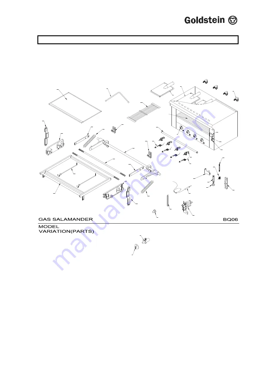
Page 14: ...IM054B2 June 2010 14 5 1 1 14 23 22 21 21 13 16 16 13 22 23 7 17 19 24 20 18 15 8 12 10 8 7 6 5 29 2 27 26 31 33 32 11 9 29 25 4 OF F NO 28 11 DRAWINGS SPARE PARTS SA 48FF MODEL SA 48FF ...
Page 15: ...AY RUNNER RIGHT HAND SIDE 15 SA 00A05 SUPPORT TRAY RUNNER LEFT HAND SIDE 16 SA 00M11 SPRING GRATE FRAME 17 SA 36A02 FRAME GRIDDLE TRAY 18 SA 00M07 HOOKS SHELF 19 SA 00M16 SPRINGS HANDLE RETURN 20 SA 00M01 GRID RATCHET 21 SA 00M05 GRID SELECTOR 22 SA 00M02 MACHINE KNOB 23 SA 00T05 SPINDLE STAINLESS STEEL 24 SA 00T06 PIN STAINLESS STEEL RETURN SPRING 25 ESPL1500 LEAD H T L 1 5m 26 ESP00003 SPARKER 2...
Page 16: ...ial or workmanship in accordance with the warranty offered This undertaking covers the provision of labour and parts for 12 months from the date of delivery to the purchaser This undertaking applies only to state capitals Remote areas are not covered by this commitment and special enquiries should be made Note Travel time not covered by warranty To the maximum extent permitted by law any liability...
Page 17: ... 47 Stubbs Rd Nautilus Complex Kensington Unit 12 Victoria 3031 210 Queensport Road Murrarie Qld 4172 Phone 03 9372 6577 Phone 07 3890 1811 Fax 03 9372 6477 Fax 07 3890 1788 South Australia Western Australia Suite 26 Unit 2 283 287 Sir Donald Bradman Drive 9 Meares Way Brooklyn Park Canning Vale South Australia 5032 Western Australia 6155 Phone 08 8238 3423 Phone 08 9456 0559 Fax 08 8238 3400 Fax ...